Mechanical, Electrical, Recalibration after installation – Warner Electric B30 Single Range Tensioncells User Manual
Page 10
10
Warner Electric • 800-825-9050
P-2012-4 • 819-0404
Mechanical
1. Has the tension measuring system been
changed?
a. An increase or decrease in strip tension
(Refer to A on the calibration sheet for
specified strip tension.)
b. An increase or decrease in the wrap angle.
(Refer to B on the calibration sheet for the
specified wrap angle.)
If the above parameters have been changed
enough to prevent the unit from operating within
the limits of the fixed. Mechanical Stops,
replacement of the tensioncells required. For
this modification, the Tensioncell should be
returned to the factory with complete
specifications.
2. Are the loadcells mounted securely?
3. Is tension measuring roll in proper alignment
and does it turn freely?
4. Are bearings and seals free of all binding and
stickiness? Are they worn?
Electrical
1. Are LVDTs receiving correct input voltage?
Check line voltage, fuses or circuit breakers,
and power switches. Check power supply
output and voltage to LVDTs.
2. Are all connections secure?
Check for continuity. Retighten all
connections. Recheck operation.
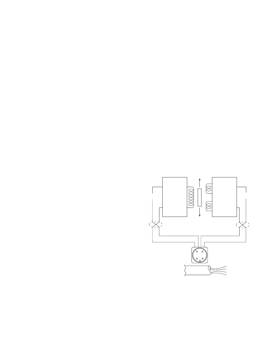
3. Are LVDTs open or shorted?
To check, turn off power and disconnect the input
and output leads. Check coil continuity and
resistance. (Refer to Figure 11)
a. Pin A to Pin B (Primary Coil) should be in
excess of 2 megohms.
b. Pin A or Pin B to LVDT shell should be in
excess of 5 megohms.
Recalibration after Installation
Wall Mounted Tensioncells can be relocated
around the center of the measuring roll. The
theory of this operation is explained in the
Description of Operation on Page 5. If this
procedure cannot accomplish the necessary
changes because the tension requirements are
extremely different than the original application,
it will be necessary to return the Tensioncells to
the factory for a different Tensioncell.
Black - (2)
Red + (1)
Green (3)
Blue (4)
Input
Output
X Twisted Leads
A B
Oscillator
Demodulator
P1
S1
S2
X
X
When Supplied
with Cable
(1) Red + DC
(2) Black – DC
(3) Green – Signal
(4) White + Signal
C D
B
A
C
D
Figure 11
c. Pin C to Pin D (Secondary Coil) should be
approximately 20,000 ohms.
d. Pin C or Pin D to LVDT shell should be in
excess of 5 megohms.
If LVDT circuits are open or shorted, replace the
Tensioncell LVDT. Contact Warner Electric with
Tensioncell model number and serial number.