Warner Electric AC10 Measuring System User Manual
Page 14
14
Warner Electric • 800-825-9050
P-2012-2
7. Adjust Out 1 0%
a.
Connect a digital voltmeter between J6-3
Out 1 and J6-4 Gnd.
b. Press the UP or DOWN arrow key (and
RAPID key if necessary) until the desired
no load output voltage is attained.
c.
Press ENTER.
8. Adjust Out 2 0%
a.
Connect a digital voltmeter between J6-1
Out 2 and J6-2 Gnd.
b. Press the UP or DOWN arrow key (and
RAPID key if necessary) until the desired
no load output voltage is attained.
c.
Press ENTER.
Note: Steps 9 through 12 can be performed
with 50% or 100% load applied when setting
Output #1 and Output #2 voltage. Refer to
the table at the right for minimum resultant
load required for setup before proceeding.
9. Apply Load 100%
a.
Press the UP or DOWN arrow key to tog-
gle between 50% or 100%. When desired
percentage is displayed.
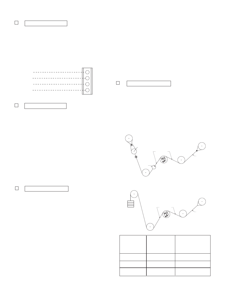
The illustrations at the right show two pull
test methods. These tests are used to
apply a load representative of the web
tension. The load should be equal to the
percentage of the full load selected (50%
or 100%).
b. Thread a non-stretchable rope over the
center of the tension measuring roll simu-
lating the web path.
Out 2
Gnd
Out 1
Gnd
J6
Output #2 ( -10 to +10 VDC)
Common
Output #1 ( -10 to + VDC)
Common
1
2
3
4
Note: All rolls used in the pull test
should be free running rolls.
c.
With one end of the rope secured, hang a
weight equal to the full load tension. (50%
if selected)
A crane scale may be used to apply the
required load.
d. Press
ENTER.
10. Adjust Out 1 100%
a.
Connect a digital voltmeter between J6-3
Out 1 and J6-4 Gnd.
b. Press the UP or DOWN arrow key (and
RAPID key if necessary) until the desired
full load output voltage is attained.
c.
Press ENTER.
Model
Max Load
Min. Tension
Capacity
Load for Setup
(Pounds)
(Pounds)
ACIDA
60
4
ACIDB
170
10
ACIDC
500
30
Scale
W eb Path
Roll
Rope
W eb Path
Roll
Rope
W eights for
Max. Tension
Table 2