Warner Electric AC10 Measuring System User Manual
Page 11
11
Warner Electric • 800-825-9050
P-2012-2
J2 to W2 Tensioncell Connection with Warner
Electric supplied cable
Terminal
Label
Description
Wire Color
J2-1
Sig
AC signal from LVDT
Yellow
J2-2
Sig
AC signal from LVDT
Pink
J2-3
Exc
Excitation to LVDT
Brown
J2-4
Exc
Excitation to LVDT
White
J2-5
Gnd
Shield
Shield
J3 Input Power (115/230 VAC, 1-PH, 50/60 Hz)
Terminal Label
Description Wire
Color
J3-1
Gnd
Ground
Green
J3-2
L1
L1 (230V) or Hot (115V)
Black
J3-3
L2
L2 (230V) or Neutral (115V) White
The input voltage selector switch must corre-
spond to the voltage of the input power
source.
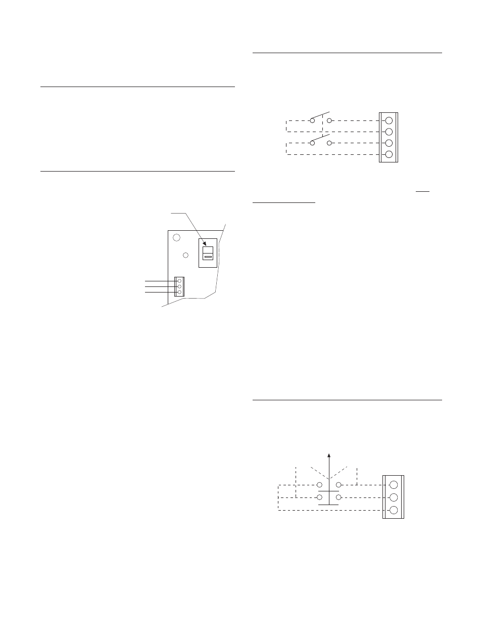
J4 AC Power Switch and/or Power Indicator
Terminal
J4 provides the terminal connection for an exter-
nal AC Power Switch and/or power indicator. The
indicator should not draw more than 40 milliamps
of current. J4 may also be used to supply AC
power to a digital voltmeter by connecting the
meter between J4-2L1 and J4-2L2.
Note: If an ON-OFF switch is not used,
jumpers must be installed from J4-2L1 to
J4-1L1 and from J4-2L2 to J4-1L2 for
proper operation.
Gnd
L1
L2
J3
230V
1
2
3
Make sure voltage select
switch is in proper position
Input Power single phase
115 or 230 VAC
X
X
2-Only
1-Only
Gnd
J5
Cell #2
Cell #1
Total
1
2
3
Terminal
Label
Description
J4-1
2L1
(Switched) Line 1
J4-2
1L1
(Hot) Line 1
J4-3
2L2
(Switched) Line 2
J4-4
1L2
(Hot) Line 2
J5 Cell#1/Total/Cell#2 Switch Terminal (For
Output #2 only)
J5 provides the connections for an external
three-position switch with two normally open
contacts. When used in conjunction with a
remote meter, the switch allows the user to
monitor total tension or the tension applied to
either Tensioncell. The meter should be connect-
ed to Output #2 at J6, terminals Out2 and Gnd.
With the switch in the normally closed position,
Output #2 will indicate the total tension. In the
Cell#1 position, Output #2 switches to indicate
the tension measured by the W1 Tensioncell.
Changing to the Cell#2 position switches Output
#2 to indicate the tension applied to the W2
Tensioncell.
Terminal
Label
Description
J5-1
2-Only
(Switched) tension W1
J5-2
1-Only
(Switched) tension W2
J5-3
Gnd
Ground
2L1
1L1
2L2
1L2
J4
1
2
3
4