Warner Electric L Series 310 User Manual
Page 6
6 Warner Electric Europe • +33 (0)2 41 21 24 24
P-2072-WE • 2/13
5
MAINTENANCE
After some period of use involving a certain number of slipping, more or less depending on he conditions of the
application, the torque transmitted is reduced. It is therefore necessary to check this transmitted torque from
time to time as well as the state of the disc
2
and
12
and to change them if necessary.
5.1 - Disassembly
• Separate the driving and driven parts.
• Unscrew the adjusting screws
9
and wear compensation screws
10
in order to release the springs
7
.
• Remove the safety-ring
4
or the thrust-cheek
5
.
• Examine the disc. If the inner disc
2
and outer disc
12
show some wear or some distorsion or have an
irregular look caused by heating (more or less strong traces), it is necessary to change them.
5.2 - Reinstallation
Impregnate the disc with oil as explained in paragraph 6, except for exceptional use in dry conditions.
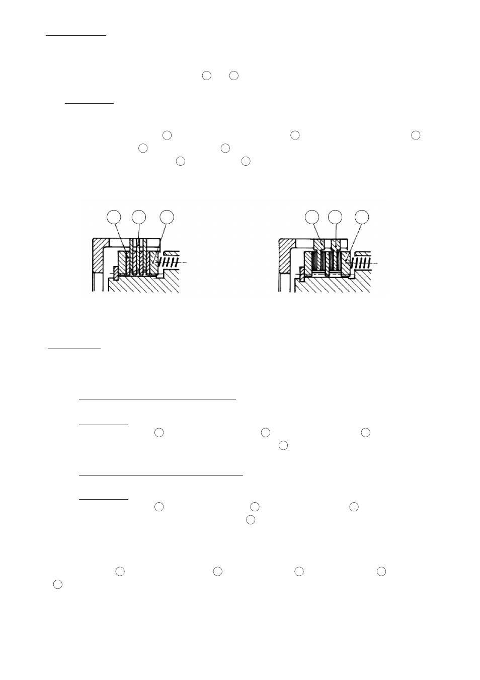
5.2.1 - Set of “B” disc (reference of the unit L-B)
Fitting order:
First the thrust-plate
3
, then a sintered inner disc
2
, then an outer steel disc
12
, and so on in the
same succession with, at the end, a sintered inner disc
2
.
5.2.2 - Set of “Gr” disc (reference of the unit L-Gr)
Fitting order:
First the thrust-plate
3
, then a lined outer disc
19
, then an inner steel disc
18
, and so on in the same
succession with, at the end, a lined outer disc
19
.
After fitting the disc,
• Place on the hub
1
the second thrust-plate
3
and the safety-ring
4
or the thrust-cheek
5
with the screws
6
, depending on the type of unit.
2
12
3
18
19
3
L.B
L. Gr