Warner Electric L Series 310 User Manual
Page 4
4 Warner Electric Europe • +33 (0)2 41 21 24 24
P-2072-WE • 2/13
3
ASSEMBLY:
The bores of the hub
1
and the spider
11
are usually machined to the H7 tolerance.
For fitting the unit on the shaft, we recommend to adopt the js6 tolerance.
The width of the hub
1
’s keyway has the JS9 tolerance.
The g6 tolerance is quite suitable for centering the spider
11
.
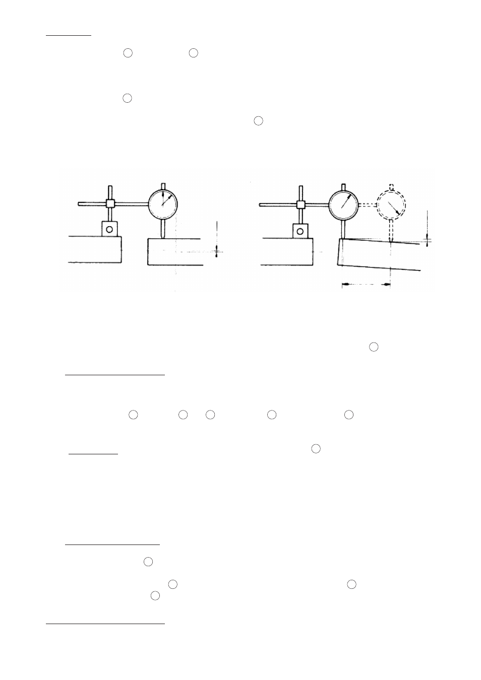
To ensure proper alignment of the two shafts, tolerance of Fig. 3 and Fig. 4 should be adhered to.
If such tolerances cannot be achieved, it is advisable to combine the limiter with an elastic coupling between
the motor and the driven machine.
The unit is sold in an assembled state. Before fitting it on the machine, remove the spider
11
.
3.1 - Fitting of the driving part:
After fitting the key on the driving shaft:
• Slide the block : hub
1
with discs
2
and
12
, thrust-cheek
5
, adjusting washer
8
, etc...into position on the
shaft.
IMPORTANT: When doing this, never strike on the end of the hub
1
without placing a piece of
soft alloy between the hub and the system chosen for pushing the above block on the
shaft.
• Lock this block against axial movement by means of safety-ring, a slotted round nut with a brake-washer or
a washer with a screw, which will have to be locked by using a thermoplastic liquid, like for example
“LOCTITE 243”
3.2 - Fitting of the driven part:
• Center and fix the spider
11
on the part to be driven (lock the fixing screws with LOCTITE locking product)
• Allow the slots of the outer disc
12
, to fit the corresponding notches of the spider
11
and put together the
driving part and the spider
11
.
Make sure the length “L” be kept
Driving Shaft
Driven Shaft
Fig. 3
0,02
Driving Shaft
Driven Shaft
Fig. 4
100
0,05