Warner Electric L Series 310 User Manual
Page 5
Warner Electric Europe • +33 (0)2 41 21 24 24
P-2072-WE • 2/13 5
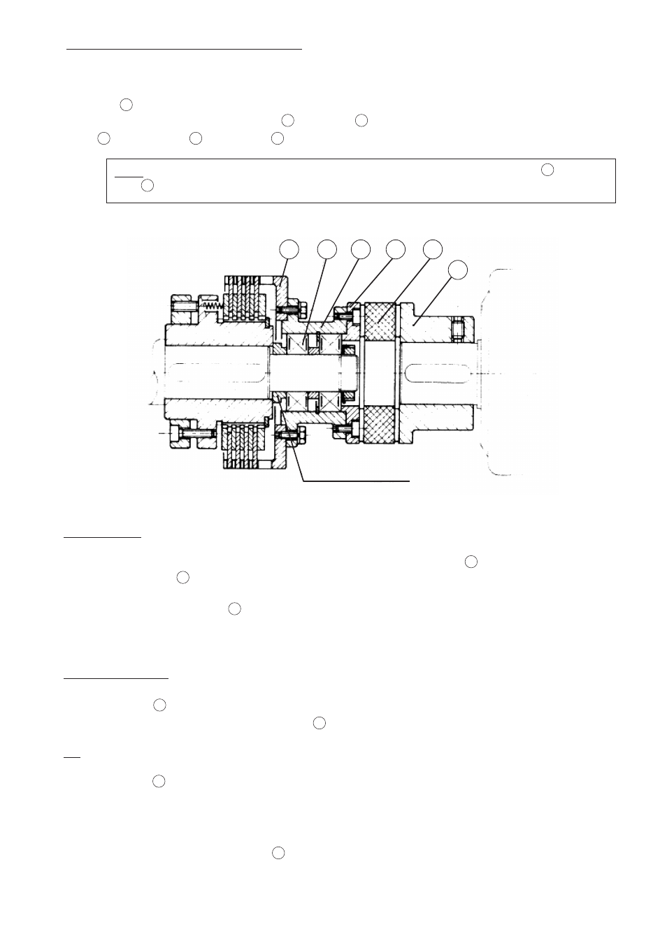
3.3 - Fitting with elastic coupling : L series 110.05
This fitting method ensures a perfect alignment of both sides of the torque-limiter when coupling two shaft-ends.
The spider
11
is centered and fitted on the shaft-end on which the other side of the unit is assembled (see
chapter 3.1) by means of two ball-bearings
13
and a case
14
bound to the elastic coupling, which consists of a
flange
15
, a toothed ring
16
and a sleeve
17
.
Note: After the unit has been fitted on the shaft, the screws used to fasten the flange
15
onto the
case
14
will have to be secured by the customer with LOCTITE - 270
4
ADJUSTMENT
The limiter is adjusted to be calibrated torque by acting on the adjusting screws
9
after unscrewing the wear
compensation screws
10
:
• Screwing the adjusting screws
9
(clockwise) increases the torque.
• Unscrewing them (anti-clockwise) reduces it.
Proceed as follows:
• Lock the spider
11
• Measure the static or slipping torque of the hub
1
by means of a torque wrench.
Or:
• Submit the hub
1
to a torque (by using a lever arm for example) :
• Measure this torque with a pair of scales or with a mass equal to the torque to be limited and placed at the end
of a one-meter long lever arm.
• Check dimensions “Z” in several places : it should be the same for all.
• Tighten the wear compensation screws
10
after adjusting the torque.
11
13
14
15
16
17
Distance - piéce