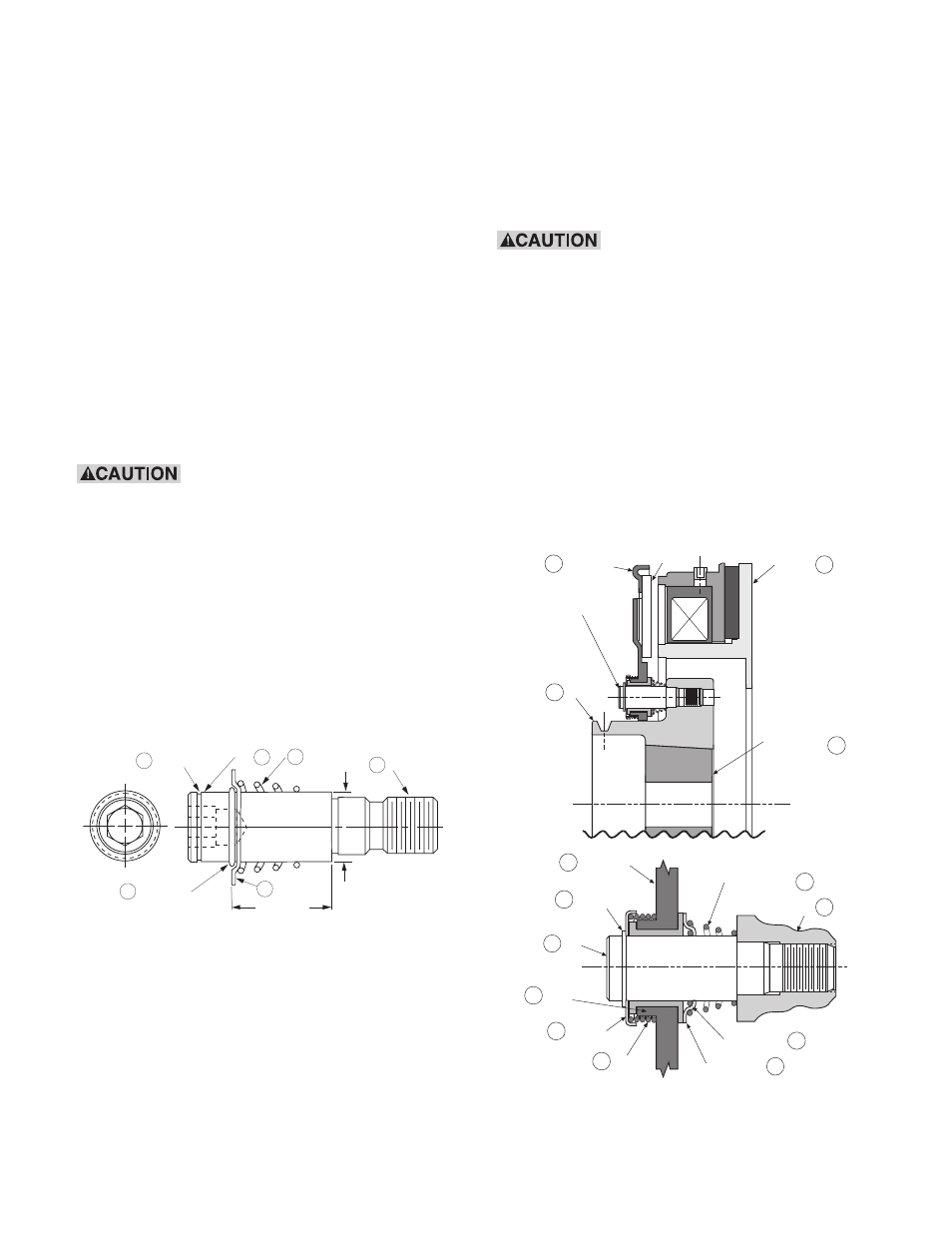
Figure 3 – Warner Electric Autogap New ER-1225 and ER825 User Manual
Page 4
4
Warner Electric • 800-825-9050
P-230-1
Step 7:
Use hex key wrench to remove the
four drive pins (item 4). Discard four
pins together with four detent rings
(item 7), four detent cups (item 6), and
four yellow springs (item 5). Do not
discard hub.
Note: Do not remove the magnet from the
motor.
Assembling the New Autogap
Components with the existing Hub and
Armature
(See Figures 2, 3, 4, & 5).
Note: Steps 1 through 8 below are to be done
on a bench away from the motor.
During Steps 1 through 3,
ensure that the detent ring (item 7) does not
slide off the pin (item 4). Make sure the yel-
low spring (item 5) is not pinched between
the pin (item 4) and the hub (item 2).
Step 1:
Each new detent ring (item 7) is
assembled on each new pin (item 4) at
the factory. Ensure that each detent
ring is approximately 7/8 inch away
from the shoulder of the pin. If it is
not, slide the detent ring into position
as shown in Figure 2.
Figure 2
Step 2:
Assemble each new detent cup (item
6) with concave side towards the
detent ring (item 7) and each new yel-
low spring (item 5) onto each new pin
(item 4) as shown in Figure 2. Make
sure the small end of the yellow spring
is on the 5/8 inch diameter as shown
in Figure 2.
Step 3:
Following the manufacturer’s instruc-
tions, apply Grade 242 Loctite to each
of the new pin threads (item15) and,
using the hex key wrench, screw the
four new pins (item 4) into the hub
(item 2). Tighten each pin to 45-50
lb.ft. of torque using a torque wrench.
During Steps 4, 5, 6, 7 and 8, do
not slam the armature down on the detent
cups. Slamming the armature on the detent
cups can deform the cups and cause the
armature to rub during operation.
Step 4:
Slide the previously saved armature
(item 3) onto the pins, and gently
push down on the armature towards
the hub (item 2) until it bottoms out.
Step 5:
Assemble each new red straight
spring (item 8) onto each armature
boss (item 13) as shown in Figure 3,
Detail B.
Detent RIng
7
Pin 4
Yellow
Spring
5
.875 ± .030
5/8 Diameter
Detent Cup
6
Pin Groove
16
Threads
15
Face of the
Armature
Armature
3
See Detail B
Hub
Magnet
Taper Lock
Bushing
2
11
1
3
10
4
9
8
5
2
7
6
Armature
Retainer
Ring
Pin
Follow
Up Cup
Armature
Boss
Red
Spring
Detent Ring
Detent Cup
Yellow Spring
Hub
Detail B
13
Figure 3