Warner Electric Autogap New ER-1225 and ER825 User Manual
Page 2
2
Warner Electric • 800-825-9050
P-230-1
Contents
Introduction . . . . . . . . . . . . . . . . . . . . . . . . . . . 2
Kit Parts List . . . . . . . . . . . . . . . . . . . . . . . . . . 2
Disassembling Armature/Hub Assembly . . . . . 3
Assembling the New Autogap . . . . . . . . . . . . . 4
Warranty . . . . . . . . . . . . . . . . . . . . . . Back Page
Failure to follow these
instructions may result in product dam-
age, equipment damage, and serious or
fatal injury to personnel.
Introduction
This instruction sheet provides detailed instruc-
tions for the replacement of existing autogap
assemblies with new design autogap assemblies
on Warner Electric® ER brakes for Montgomery-
Kone®
Note: Please review the entire installation proce-
dure prior to starting any work.
Please follow these instruc-
tions carefully to ensure proper operation.
Failure to comply with these instructions can
result in damage to property and injury or
even death to personnel.
Applying power to the brake
will release its hold on the escalator and may
allow it to move. To prevent escalator move-
ment and the damage and/or injury that may
result, the escalator must be held in place by
another means.
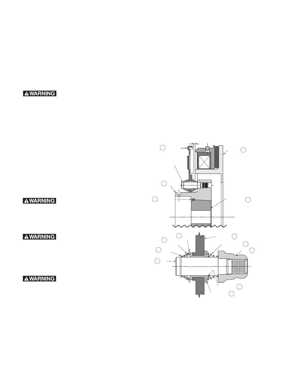
Keep fingers clear of the air
gap area between the magnet (item 11) and
the armature (item 3) - as the armature will
be pulled sharply toward the magnet after the
gap between them is closed to approximately
1/8 inch. See Figure 1. Injury can result if fin-
gers are pinched between the armature and
magnet.
3
2
11
1
Armature
See Detail A
Hub
Magnet
Taper Lock
Bushing
9
8
10
4
3
5
2
7
6
Follow
Up Cup
Blue
Spring
Retainer
Ring
Pin
Armature
Yellow Spring
Hub
Detent Ring
Detent Cup
Detail A
12 Set Screw
Airgap
Figure 1