Warner Electric Autogap New ER-1225 and ER825 User Manual
Page 3
3
Warner Electric • 800-825-9050
P-230-1
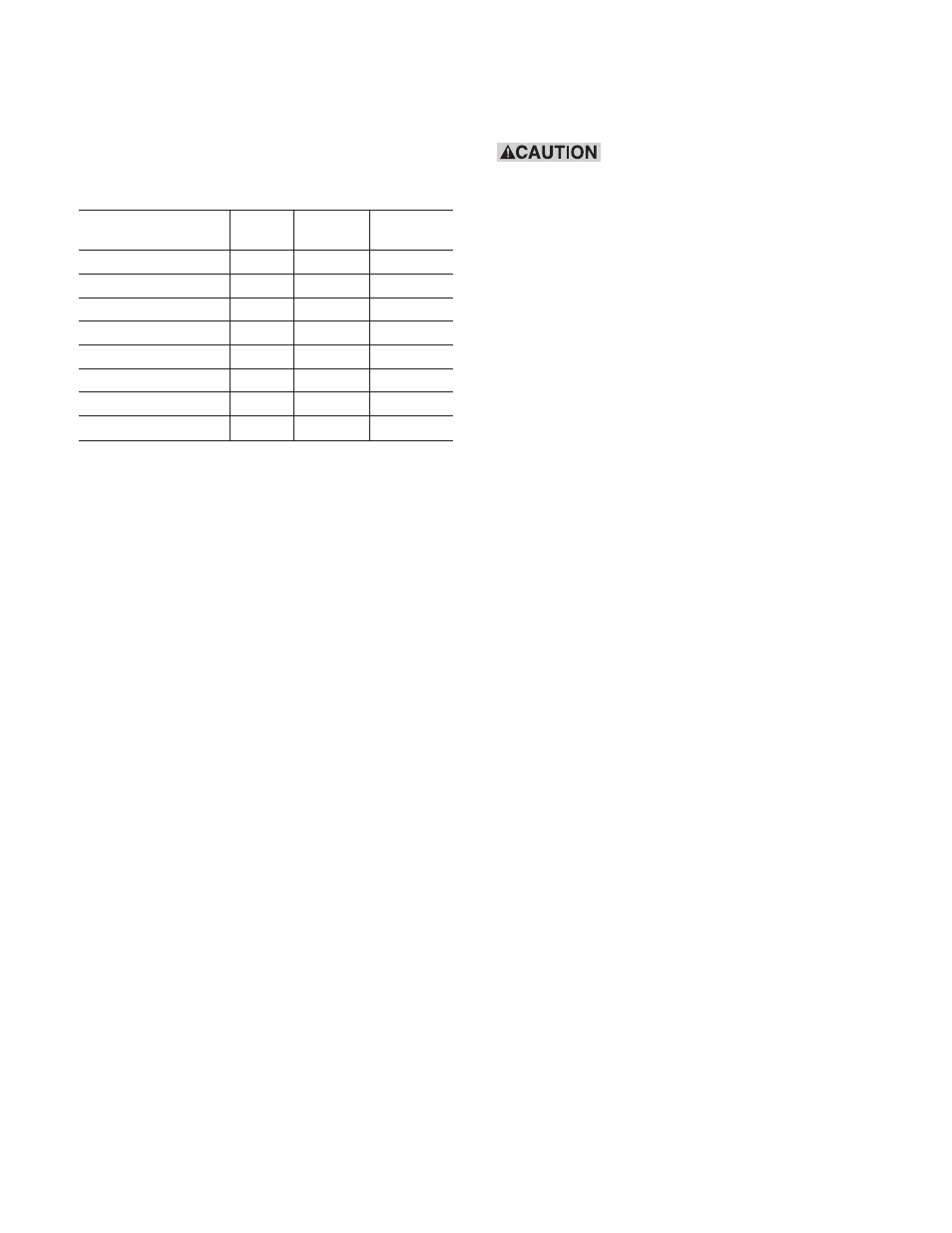
The kit part number for ER-825 is 5250-101-008
and for ER-1225 is 5252-101-005. The kit
includes the following parts.
Kit Parts List - See Figure 3
(Item
Model 825 Model 1225
Name
No.)
(Qty)
(Qty)
Pin & detent assembly
4 & 7
3
4
Detent Cup
6
3
4
Yellow Conical Spring
5
3
4
Red Straight Spring
8
3
4
Follow Up Cup
9
3
4
Retainer Ring
10
3
4
Instruction Manual
1
1
Claim Form
1
1
Tools required (not included)
• 1/4" Hex key wrench for taper lock bushing
set screws – ER-1225.
• 3/16" Hex key wrench for taper lock bushing
set screws – ER-825.
• 5/16" Hex key wrench for pins.
• 7/32" Hex key wrench for mounting screws.
• Tube Grade 242 Loctite.
• Snap ring pliers, external.
• Torque wrench minimum 200 lb.ft. reading
– ER-825.
• Torque wrench minimum 400 lb.ft. reading
– ER-1225.
• 3 steel shims, equal thickness, not less than
1/16", nor greater than 1/8".
• Small hammer (approximately 8 ounce).
• Drift
Disassembling the Armature/Hub
Assembly (See Figure 1)
Do not pry the armature away
from the magnet. If armature is distorted the
entire brake must be replaced.
Note: Steps (1) and (2) are to be performed at
the motor and (3), (4), (5), (6) and (7) are to be
performed on a bench away from the motor.
Note: Make sure power to the brake is turned
off. See Figure 1 for the following seven
steps.
Step 1:
Loosen the taper-lock bushing (item1)
on the motor shaft.
To loosen, remove both set screws
(item 12) from the taper lock bushing
(item 1) using a hex key wrench. Insert
one set screw into the previously
vacant hole in the taper lock bushing
and tighten this screw until the bush-
ing is loosened in the hub (item 2). If
the bushing does not loosen, tap on
the hub with a drift and small hammer.
Step 2:
Apply power to the brake. The arma-
ture will then spring away from the
magnet. If it does not, check electrical
connections and release voltage per
Montgomery-Kone® instructions.
Remove taper lock bushing (item 1)
and armature assembly (items 2 & 3)
from the motor shaft. Set the bushing
aside. Do not discard the bushing.
Step 3:
Remove the retainer rings (item 10)
from pins (item 4). Discard rings.
Step 4:
Remove the blue conical springs (item
8). Discard them.
Step 5:
Remove the follow-up cups (item 9).
Discard them.
Step 6:
Remove the armature (item 3) and set
it aside.
Do not discard.