Electrical connections, Ptb-bl3 wiring, This momentarily closes contacts k – Warner Electric PTB-BL3 User Manual
Page 6: This in turn applies voltage to relay k, And k, And opens contacts k, And /or k, Figure 7 wiring (ptb-bl3 brake only)
6
Warner Electric • 800-825-9050
819-0368
Electrical Connections
To avoid injury (or even death),
always make certain all power is off before
attempting to install or service the control or
any electrical equipment.
The clutch and brakes operate on DC voltage.
Warner Electric offers a full line of AC powered
controls to meet the needs of almost every
application. The service and installation instruc-
tions included with each Warner Electric control
show the proper electrical connections for the
units. Do not use the varistor supplied with the
unit if you are using a Warner Electric control.
Warner Electric controls have built in suppres-
sion.
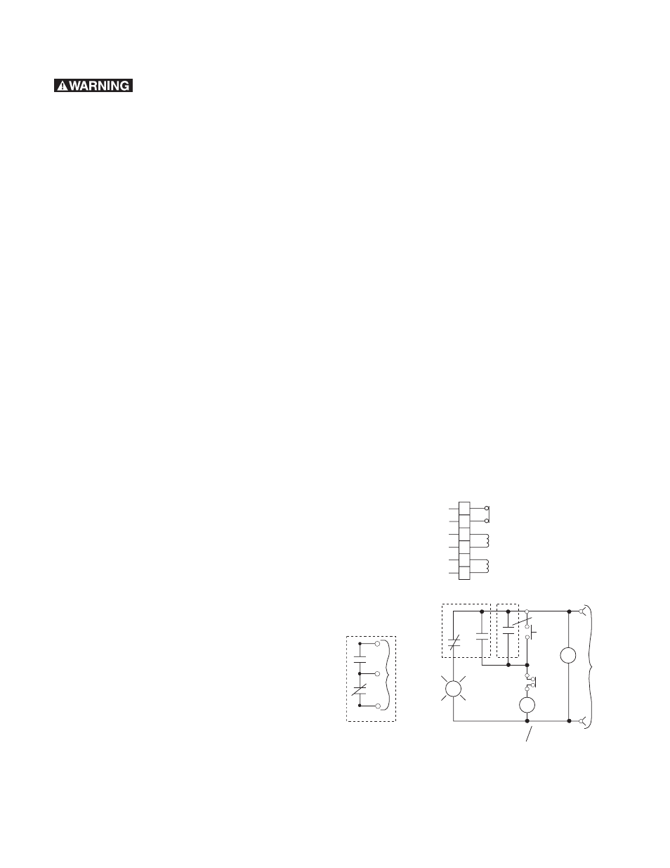
Each PTB-BL3 brake has a cooling fan and a
thermal switch. Connect these items according
to Figure 7.
Use appropriate terminal connectors when
wiring to the terminal block. After connecting the
terminal, cover it with the attached rubber cap
so that no bare wire is exposed.
After wiring your Magnetic Particle clutch or
brake, confirm that the control circuit is func-
tioning. Without rotating the input shaft, check
for voltage at the unit when the control output is
turned on. If appropriate, set the current for the
proper output. Your magnetic particle unit is
now ready for operation. For additional informa-
tion on start up and maintenance, see page 9 of
this manual.
PTB-BL3 Wiring
The PTB-BL3 units are offered with a normally
closed thermal switch. This switch can be used
to protect the unit from overheating. It is not
recommended that this switch be connected in
series with the unit, because the opening of the
thermal switch on the output side of the control
may damage the control.
Figure 7 shows one possible way of using the
switch in a shutdown circuit. Under normal
operation, when power is applied to the circuit,
voltage is applied to the interval-on-relay, K
S
.
This momentarily closes contacts K
SA
. This in
turn applies voltage to relay K
T
. This double pole
double throw relay closes contacts K
TA1
, and
K
TB1
and opens contacts K
TA2
and K
TB2
. These
contacts will remain in this state unless power is
removed or the thermal switch opens. If the
switch opens, the thermal shutdown indicator
will be activated and the state of K
TB1
and /or
K
TB2
will shut down the system. After correcting
the cause of the thermal shutdown, the thermal
reset button will reset the shutdown circuit and
power up the system.
K
S =
Interval On Relay
K
T =
DPDT Relay
Man.
Thermal
Reset
Thermal
Switch
K
TA2
K
S
K
T
K
SA
Thermal
Shutdown
Indicator
R
S
2
S
1
Power
AC
or DC
To control
circuit
or other
shut down
method
K
TB2
K
TA1
K
TB1
Typical Shutdown Circuit
Note: Select relays with appropiate voltage rating for circuit.
S
S
M
M
C
C
DC24V
115 VAC
To alarm or
Shutdown circuit
Brake Coil
Fan Motor
Thermal Switch
Terminal Block Wiring
Figure 7
Wiring (PTB-BL3 Brake Only)