Pob and ptb-bl3 brakes – Warner Electric PTB-BL3 User Manual
Page 5
5
Warner Electric • 800-825-9050
819-0368
Step 3: Mount Pulley, Sprocket, or Coupling
Note: If a pulley or sprocket is to be attached
directly to the input hub, bearings should be
installed to support the pulley or sprocket as
shown in Figure 3.
Bolt the pulley, sprocket, or coupling to the
input hub of the clutch. The pulley, sprocket,
and bolts are customer supplied. Do not block
ventilation openings.
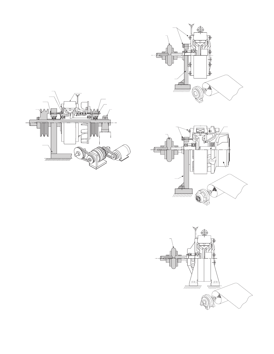
Figure 3*
PHC-R Clutches
POB and PTB-BL3 Brakes
For mounting dimensions, please refer to pages
14-16 of this service manual.
Step 1: Bolt Brake in Place
Mount the brake to a vertical surface using cus-
tomer supplied fasteners. See Figures 4 and 5.
A flat horizontal mounting surface is required for
foot mounted POB size 80 brakes. See Figure 6.
Step 2: Make Mechanical Connections
Mount couplings, pulleys, or sprockets to the
male shafts per the manufacturers' recommen-
dations. The pulleys, sprockets, and couplings
are customer supplied.
Capscrews
Output
Pulley
Mounting
Bracket
Locking
Nuts
Input Pulley
Capscrews
(Field Restraining)
Pillow Block
Field Housing
Ventilation Openings
Flexible
Coupling
Mounting
Bracket
Capscrews
Flexible
Coupling
Mounting
Bracket
Capscrews
Electric Blower
Single-Phase 110V
Heat Pipe
Figure 4*
POB Brakes (Except POB-80)
Figure 5*
PTB – BL3 Brakes
Figure 6*
POB-80 (Foot Mount)
*Note: Shaded items are customer supplied.
Flexible
Coupling