Warner Electric Preassembled Clutch_Electrically Released Brake Module User Manual
Page 4
4 Warner Electric • 800-825-9050
819-0346 • P-273-2
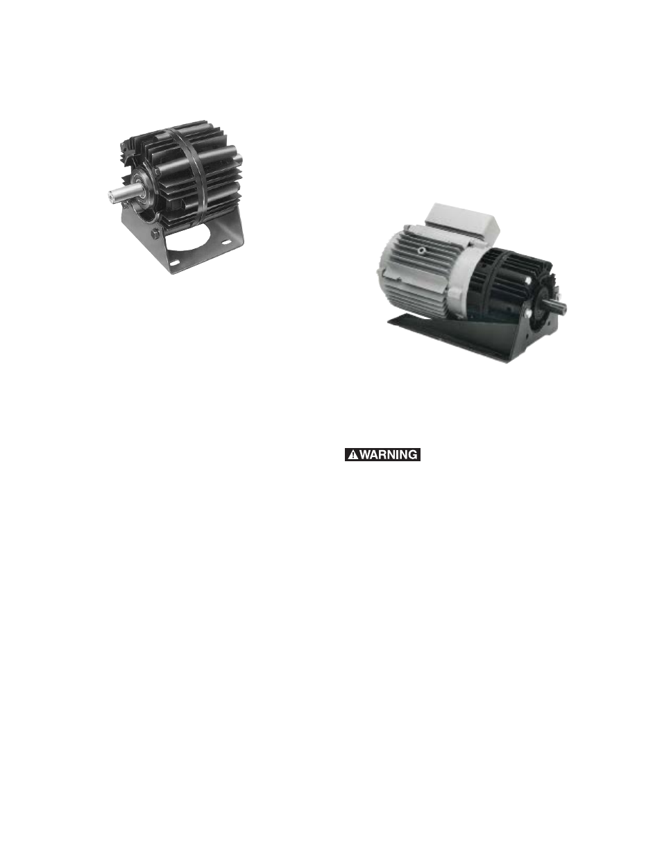
Installing the Base Mount
Unimodules 2030 FBC can be base-mounted
(Figure 5).
Figure 5
A. Mount each Unimodule so that the base is
located below the ventilation holes. A pilot
diameter on the end of each Unimodule mates
with pilot diameters on the base.
B . Secure the base to the Unimodule with the
four (4) bolts provided. (18 to 22 ft. lbs. for 50
and 180 sizes, 40 to 45 ft. lbs. for 210 size.)
Installing the Motor Mount (M)
A Motor Mount (M) can be installed to the
Unimodule output end to provide a foot
mounting for the complete assembly of
Unimodule and motor.
Size 50 and 180
A. Remove the two (2) long hex head bolts
from the side of the Unimodule toward the
ventilation holes .
B. Mount the Unimodule on the Motor Mount so
that the base of the Motor Mount is under-
neath the Unimodule and motor (Figure 6). A
pilot diameter on the Unimodule mates with a
pilot diameter on the Motor Mount .
C . Secure the Motor Mount in place with two (2)
longer mounting bolts (30 to 35 ft lbs.) and the
two shorter bolts (18 to 22 ft. lbs.) all pro vided
in the kit .
Size 210
A. Mount the Unimodule on the Motor Mount so
that the base of the Motor Mount is underneath
the Unimodule and motor (Figure 6). A
pilot diameter on the Unimodule mates with a
pilot diameter on the Motor Mount .
B. Secure the Motor Mount to the Unimodule with
three (3) bolts provided. (40 to 45 ft. lbs.)
Figure 6
Electrical Connections
To avoid injury (or even death),
always make certain all power is off before
attempting to install or service this control or
any electrical equipment.
The Unimodule is provided with one conduit
connection hole, threaded for standard 1/2”
conduit connectors . Both the clutch and the
brake lead wires are brought out through this
opening. The conduit box accessory kit, P/N
5370-101-042, provides two conduit connection
holes for standard 1/2” conduit connectors .
The clutch and brake coils operate on DC
voltage. The brake must be controlled by an
adjustable current or voltage supply for optimum
release . Warner Electric offers a complete
line of controls to meet the needs of almost
any application. The service and installation
instruction, included with each Warner Electric
control detail the proper electrical connections.