Warner Electric Preassembled Clutch_Electrically Released Brake Module User Manual
Page 2
2 Warner Electric • 800-825-9050
819-0346 • P-273-2
Contents
Introduction . . . . . . . . . . . . . . . . . . . . . . . . . . .2
Mounting to a Motor . . . . . . . . . . . . . . . . . . . . .3
Mounting to a Reducer . . . . . . . . . . . . . . . . . . .3
Installing the Base Mount . . . . . . . . . . . . . . . . .4
Installing the Motor Mount . . . . . . . . . . . . . . . .4
Electrical Connections . . . . . . . . . . . . . . . . . . .4
Start-Up . . . . . . . . . . . . . . . . . . . . . . . . . . . . . .5
Coil Data . . . . . . . . . . . . . . . . . . . . . . . . . . . . . .5
Warranty . . . . . . . . . . . . . . . . . . . . . .back cover
Install your specific modular combination
according to the installation steps specified in the
table. Use only those steps indicated for each
combination.
The 1020 and 1040 UniModules are furnished
with a special hardened key. It is strongly rec-
ommended that this key be used with the motor
shaft to avoid damage to the shaft and rotor hub.
The size 210 UniModules require an adapter ring
to be mounted to the motor prior to mounting the
1020 or 1040 UniModule. Adapter and mounting
hardware are provided with the UniModule
assembly.
Note: The equipment covered by this service
manual must be installed in accordance with
these instructions. Failure to do so may dam age
the equipment and void the warranty.
Introduction
Warner Electric’s Unimodule has been designed
to NEMA standards and can be installed with all
standard power transmission drive systems.
Before installing the Unimodule to a motor or
reducer, make certain that the UM Unimodule
size and NEMA frame dimensions match
according to the following chart.
Corresponding
NEMA Frame Sizes
C-Face
UM
Old
New
Shaft
Pilot
Size
NEMA
NEMA
Dia.
Dia.
50
56 C
48 Y
5/8
4 1/2
100
56 C
48 Y
5/8
4 1/2
180
182 C
143 TC
7/8
4 1/2
184 C
145 TC
210
213 C
182 TC
1-1/8
8 1/2
215 C
184 TC
215
213 TC
1 3/8
8 1/2
215 TC
1 3/8
8 1/2
Failure to follow these
instructions may result in product damage,
equipment damage, and serious or fatal
injury to personnel.
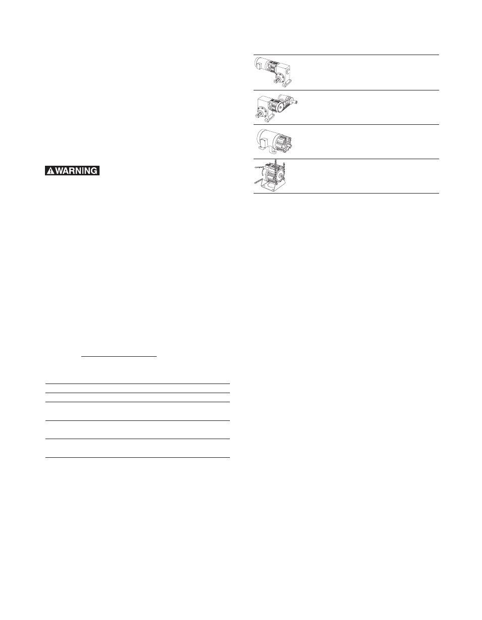
For These UM Combinations
Use These
Installation Steps:
UniModule Clutch-ER Brake
Mounting to a Motor
Between C-Face Motor
Mounting to a Reducer and
Reducer – 1020 FBC
Electrical Connections
Start Up
UniModule Clutch-Brake -
Chain or pulley Drive to
2030 FBC
a Reducer
Electrical Connection
Start Up
Motor Mount Unimodule
Mounting to a Motor
Clutch-Brake on a
Installing the Motor Mount
C-Face Motor - 1020-FBC-M
Electrical Connection
Start Up
Base Mounted Unimodule
Installing the Base Mount
Clutch-Brake - 2030-FBC-B
Electrical Connection
Start Up