Warner Electric Preassembled Clutch_Electrically Released Brake Module User Manual
Page 3
Warner Electric • 800-825-9050
819-0346 • P-273-2 3
Mounting to a Motor
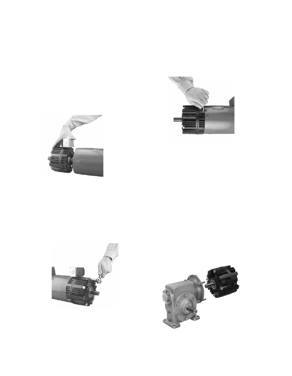
1. Replace the existing motor shaft key with
the hardened key provided with the unit. If
necessary, prick punch the keyway of the
motor shaft to keep the key from moving in the
keyway. Slide the module assembly onto the
motor shaft. (See Figure 1) Align the key in the
motor shaft with the keyway in the rotor hub.
Do not use force. If the UniModule does
not slide on freely, polish the motor shaft
sufficiently to achieve a slip fit.
Figure 1
2. The housing is provided with vent holes
which are normally placed in the down posi-
tion . Rotate the assembly to where the vent
holes are toward the bottom and insert the
four long capscrews (provided) through the
mounting holes in the housing and into the
motor face. Tighten alternately and securely.
(30 to 35 ft. lbs.)
Figure 2
3. The access hole for the Allen wrench to tight-
en the rotor setscrews is shown in Figure 3 .
Rotate the clutch rotor as necessary to insert
the wrench into the setscrews . Tighten both
screws alternately and securely. (40 to 45 in.
lbs. for 180 size, 80 to 85 in. lbs. for 50 and
210 sizes.)
Mounting to a Reducer
The output side of a Unimodule may be mounted
directly to a reducer .
A. Align the output shaft and key of the
Unimodule with the corresponding shaft hole
and keyway of the reducer. Slide the assembly
together, matching the pilot diameter on
the Unimodule with a pilot diameter on the
reducer .
B. Bolt the Unimodule to the reducer flange. The
four (4) bolts required (3/8-16 UNC-2A) are
normally furnished with the reducer. (18 to 22
ft. lbs. for 50 and 180 sizes, 40 to 45 lbs. for
210 size.)
Figure 4
Figure 3