Warner Electric ERS Electrically Released Brakes User Manual
Page 5
5
Warner Electric • 800-825-9050
819-0337
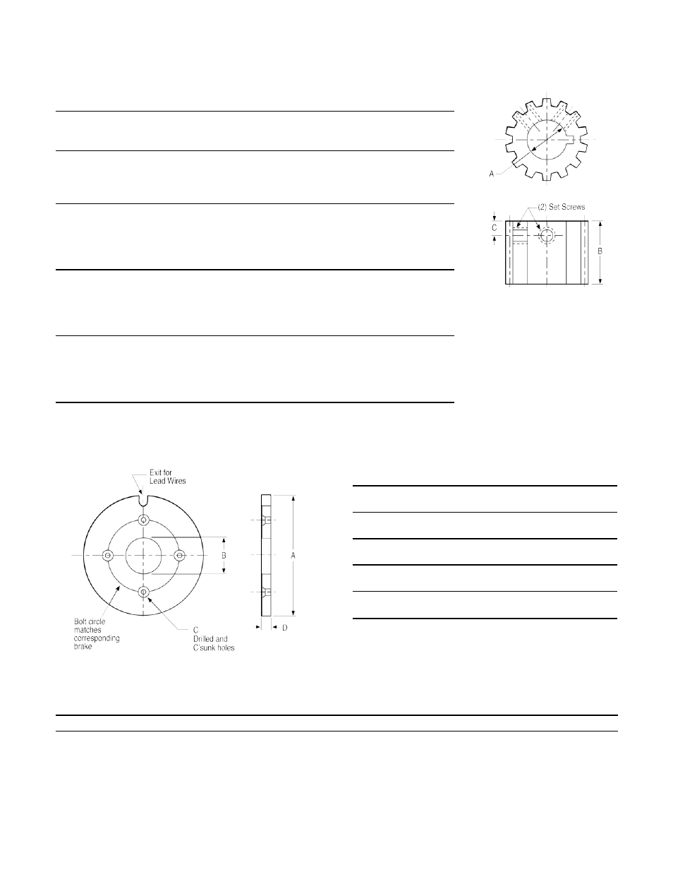
Drive Hub Data
A
Mating Key
B
C
Set
Model
Bore
(Not furnished) Nom. Nom. Screws Size Torque
ERS-26
.2525/ .2505
1/16 x 1/16
.600
.135
6-32
10
.3150/ .3130
1/16 x 1/16
x 1/8
lb. in.
.3775/ .3755
3/32 x 3/32
ERS-42
.3775/ .3755
3/32 x 3/32
.700
.150
8-32
20
.5025/ .5005
1/8 x 1/8
x 3/16
lb. in.
.6275/ .6255
3/16 x 3/16
.7525/ .7505
3/16 x 3/16
ERS-49
.3775/ .3755
3/32 x 3/32
.800
.160
10-32
36
.5025/ .5005
1/8 x 1/8
x 3/16
lb. in.
.6275/ .6255
3/16 x 3/16
.7525/ .7505
3/16 x 3/16
.8775/ .8755
3/16 x 3/16
ERS-57
.5025/ .5005
1/8 x 1/8
.800
.160
10-32
36
.6275/ .6255
3/16 x 3/16
x 3/16
lb. in.
.7525/ .7505
3/16 x 3/16
.8775/ .8755
3/16 x 3/16
1.0025/1.0005
1/4 x 1/4
ERS-68
1.0025/1.0005
1/4 x 1/4
.900
.190
1/4-20
87
1.1275/1.1255
1/4 x 1/4
x 1/4
lb. in.
1.2525/1.2505
1/4 x 1/4
1.3775/1.3755
5/16 x 5/16
1.5025/1.5005
3/8 x 3/8
Note: Hub may be located in any position on shaft as long as the external
and internal splines are 100% engaged.
A
B
C
D
Model
Nom.
Nom.
Holes
Nom.
ERS-26
4.000
.935
#4
.100
(101.6)
(23.7)
(2.6)
ERS-42
5.000
1.450
#6
.144
(127.0)
(36.8)
(3.7)
ERS-49
6.250
1.575
#8
.193
(158.8)
(40.0)
(4.9)
ERS-57
7.500
1.825
#10
.193
(190.5)
(46.4)
(4.9)
ERS-68
9.500
2.500
1/4
.224
(241.3)
(63.5)
(5.7)
(—) denotes millimeters
Note: Holes for attaching flange to mounting
surface to be provided by customer.
Troubleshooting
Symptom
Check
Brake will not release
a. Proper voltage at the brake terminal(s).
b. Correct unit voltage matched to power supply.
c. Coil continuity if proper voltage is at the brake leads.
d. Spline for binding. Friction disk must be able to move freely on mating spline.
If the above checks do not determine the cause of the failure, the brake is non-operational and must be replaced.