Specifications, Dimensions for panel mounting – Warner Electric CBC-1000 User Manual
Page 6
Range: xxx.xxx to xxxxxx
Keyboard
Sealed tactile feel, 18 positions
Program Security
Program LOCK of lines 1 - 34
Control Outputs
Type
8 Solid State, 100 mA sink max.,
24 VDC max.
Serial Interface
Type
RS-422A/485 compatible
Baud Rate
Selectable: 300, 600, 1200, 2400
Parity
Selectable: None, Odd, Even
Data
ASCII
Format
Start bit, 7 bit ASCII data, Parity bit,
Stop bit
I.D. Number
Programmable 0 to 98: Allows
multidrop systems
Diagnostics
Test 0
Keyboard Test
Test 1
Non-Volatile RAM Test
Test 2
Input Test
Test 3
Output Test
Test 4
Display Test
Test 5
Program Memory Test
Test 6
Date Code Test
Test 7
Serial I/O Test
Test 8
Return to Factory Programming
Mechanical
Enclosure
Aluminum extrusion with molded
VALOX bezel. 2.91” high x 5.67” wide x
6.03” deep overall
Weight
2.5 lbs.
Cutout
5.43” ± 0.04” x 2.68” ± 0.03”
Panel Thickness
1/16” to 1/4”
Panel Depth
5.68” minimum
Environmental
Operating Temp.
0° to +50°C (32° to 122°F)
Storage Temp.
-18° to 85°C (0° to 186°F)
Ambient Humidity
90% and noncondensing
Controller Error Codes
Error 2: Low AC Line Voltage
Error 3: Input Frequency too fast
Error 4: Processor time fully utilized
Specifications
Part No.
6060-448-001
Input Power
100 to 130 VAC, 50/60 Hz, 20VA
(200 to 260 VAC selectable)
Auxiliary Supply
12 VDC @ 175 mA
Used for powering encoder, etc.
Main Counter
Range
6 Decade
Reset Input
2 Individual with 6 decade range
Operation
Quadrature
Reset Input
External and front panel
Count Rate
(20 kHz external input frequency)
Batch Counter
Range
6 Decade
Presets
1 with 6 Decade range
Operation
Count UP by detecting Zero Speed
Reset
Through front panel only
Output
Latched, fixed to output terminal 21
Signal A and B Inputs
Input Frequency
DC, 20 kHz quadrature max.
Input Type
Single ended, Current Source
Input Logic
Times 2
Input High Level
3.25 VDC min.
Input Low Level
1.75 VDC max.
Input Impedance
1.0
Ω to common
Input current
3.25 mA steady state
Input Response
10 µs. min high and low time
Control Inputs
Input Frequency
DC to 20 Hz max. each input
Input Type
Single ended, current sinking
Input Logic
Both Edge and Level sensitive
as defined by input use
Input High Level
10 VDC min. to 20 VDC max.
Input Low Level
0 VDC min. to 2 VDC max.
Input Impedance
4.7
Ω pullup to +12 VDC
Input Current
2.5 mA steady state
Input Response
25 ms. make and break time
Display
Decade
7 Decade, 0.6" red LED
Decimal Point
User programmable
4
Warner Electric • 800-825-9050
P-275 • 819-0496
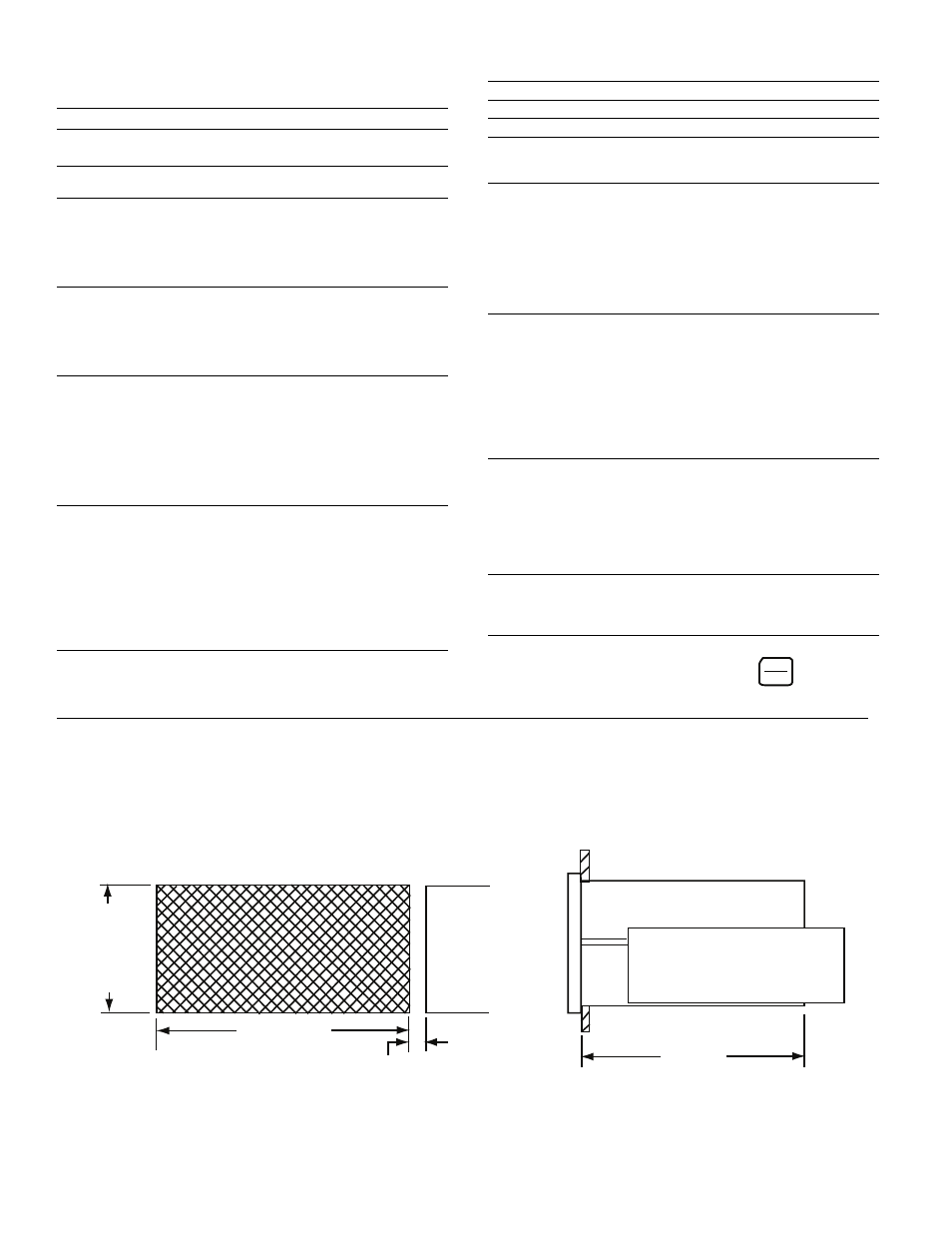
Dimensions For Panel Mounting
RESET
CLEAR
Press
to clear error code
Make panel cutout. Affix adhesive gasket (if required) to panel. Remove
panel straps and slide unit thru cutout. Slide panel straps into enclosure
guides. Thread 5/8” long hex washer head screws into guides using a
3/16” hex driver and tighten securely.
5.43 ± 040
(138 + 1, -0 mm)
allow 0.32” (8mm) each
side between cutouts
2.68
±
.030
(68
+
1,
-0
mm)
5.68
(144 mm)