Installation, With auxiliary power supply (rear view), Typical sensor wiring – Warner Electric CBC-1000 User Manual
Page 19: Typical relay wiring
17
Warner Electric • 800-825-9050
P-275 • 819-0496
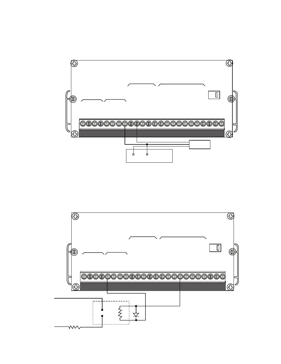
Installation
With Auxiliary Power Supply (Rear View)
Typical Sensor Wiring
14
+12V
COM
Auxiliary
Power
Supply
Sensor
Note: Use shielded
wire on sensor
when far away
from control to
minimize noise.
-12V
+12V
Relay
115 VAC
Load
H
N
115 VAC
Serial
Data
Signal
Inputs
Control
Inputs
Control
Outputs
Power
Serial
Data
Signal
Inputs
Control
Inputs
Control
Outputs
Power
1
2 3
4
5
6
7 8
9 10 11 12 13 14 15 16 17 18 19 20 21 22 23 24
1
2 3
4
5
6
7 8
9 10 11 12 13 14 15 16 17 18 19 20 21 22 23 24
RXD
-
RXD
+
TXD
-
TXD
+
+12V
Sig
A
Sig
B
COM
Start
Early
W
arning
Continuous/Single
Reset
COM
Start
Brake
On
Zero
Speed
Zero
Speed
+
Delay
1
Aux.
Start
Batch
Complete
Hot
Neutral
Bld.
GND
Zero
Speed
+
Delay
2
Early
W
arning
RXD
-
RXD
+
TXD
-
TXD
+
+12V
Sig
A
Sig
B
COM
Start
Early
W
arning
Continuous/Single
Reset
COM
Start
Brake
On
Zero
Speed
Zero
Speed
+
Delay
1
Aux.
Start
Batch
Complete
Hot
Neutral
Bld.
GND
Zero
Speed
+
Delay
2
Early
W
arning
230
230
Typical Relay Wiring