Installation, Connection diagrams, Delay timer used as a cycle timer 16 – Warner Electric CBC-1000 User Manual
Page 18
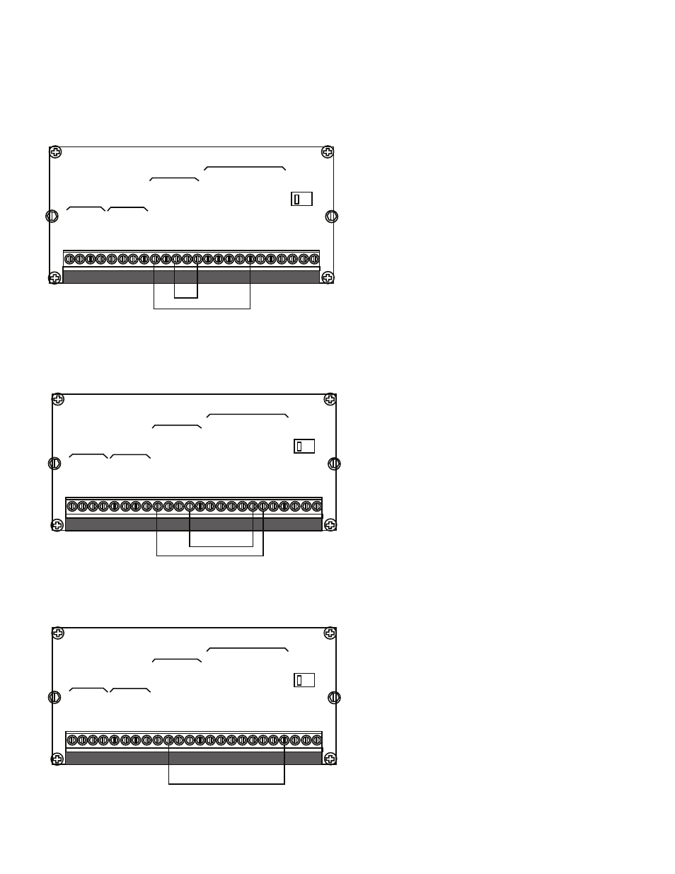
Delay Timers 1 or 2 may be used to initiate an
external start input signal and function like a cycle
timer. The delay times are programmed on lines
16 and 17 of the program mode. In the diagram,
Delay Time 1 is used to initiate the external start
input signal to begin the next operation.
Note: the CBC-1000 must be configured in the
continuous mode as shown.
Output 4, 5 or 6 (Terminals 17, 18, 19) may be
used to reset the counter in the incremental
mode. Remember, in the incremental mode
(programming line 8, auto Reset -”off”) it is
necessary to externally reset the counter at the
completion of the previous operation. In the
diagram, Delay Time 1 (programming line 16) is
used to reset the counter, Delay Time 2 to start.
The Batch Complete Output may be used to stop
operations after a preset batch count (programmed
via function key 7, see page 10). Once this batch
preset has been reached, it is necessary to reset
the batch counter (function key 6, see page 10) to
continue another batch. The batch counter can be
reset manually or automatically by programming
line 15 (refer to page 12).
1 2 3 4 5 6 7 8 9 10 11 12 13 14 15 16 1718 19 20 21 22 23 24
1 2 3 4 5 6 7 8 9 10 11 12 13 14 15 16 1718 19 20 21 22 23 24
1 2 3 4 5 6 7 8 9 10 11 12 13 14 15 16 1718 19 20 21 22 23 24
RXD
-
RXD
+
+12V
Sig
A
Sig
B
TXD
-
TXD
+
COM
Start
Stop
Continuous/Single
Reset
COM
Start
Early
W
arning
Brake
On
Zero
Speed
Zero
Speed
+
Delay
1
Zero
Speed
+
Delay
2
Aux.
Start
Batch
Complete
Hot
Neutral
Bld.
GND
RXD
-
RXD
+
+12V
Sig
A
Sig
B
TXD
-
TXD
+
COM
Start
Stop
Continuous/Single
Reset
COM
Start
Early
W
arning
Brake
On
Zero
Speed
Zero
Speed
+
Delay
1
Zero
Speed
+
Delay
2
Aux.
Start
Batch
Complete
Hot
Neutral
Bld.
GND
RXD
-
RXD
+
+12V
Sig
A
Sig
B
TXD
-
TXD
+
COM
Start
Stop
Continuous/Single
Reset
COM
Start
Early
W
arning
Brake
On
Zero
Speed
Zero
Speed
+
Delay
1
Zero
Speed
+
Delay
2
Aux.
Start
Batch
Complete
Hot
Neutral
Bld.
GND
Serial
Data
Signal
Inputs
Serial
Data
Signal
Inputs
Serial
Data
Signal
Inputs
Control
Inputs
Control
Outputs
Control
Inputs
Control
Outputs
Control
Inputs
Control
Outputs
VAC
VAC
VAC
115
115
115
Installation
Connection Diagrams
Delay Timer Used as a Cycle Timer
16
Warner Electric • 800-825-9050
P-275 • 819-0496
Batch Complete Configured to Stop Operation after Batch Preset has been Reached
Delay Timer Used to Reset the Count in the Incremental Mode of Operation