Installation instructions iq3xcite, 4 installation - configuration, Switch off – TREND IQ3xcite User Manual
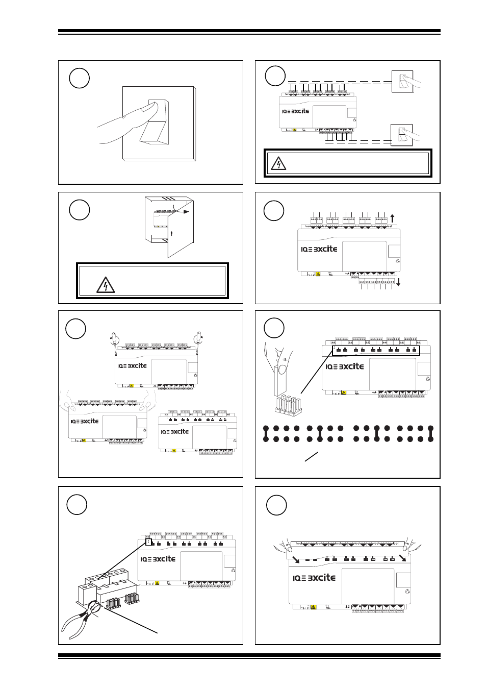
Page 7: Isolate i/o, Disconnect i/o, Open panel, Remove cover, Select input channel types, Cut screen earth (ground) link, Replace cover
7
IQ3xcite Web Enabled Controller Installation Instructions TG200626 Issue 2 21/04/08
Installation Instructions
IQ3xcite
O
I
Switch Off
1
Isolate I/O
2
4 Installation - Configuration
WARNING: The connecting leads may be
connected to supplies. Isolate before touching.
4 5 6
2
7 8 9
3
10 11 12
4
13 14 15
5
16 17 18
6
19 20 21
7
22 23 24
8
25 26 27
9
28 29 30
10
+ 0
+ 0
+ 0
+ 0
+ 0 + 0
+ 0
+ 0
+ 0
1 2 3
1
+ 0
0 V
24 V
24 V
34 35 36
12
37 38 39
13
40 41 42
14
A
31 32 33
P
11
43 44 45
15
46 47 48
16
100-240 V
OK RX
P 0 P 0
P 0
P 0 P 0
P 0
O
I
O
I
also isolate I/O of any
adjacent I/O modules
Disconnect I/O
4
Open Panel
3
A
0 V
24 V
24 V
34 35 36
12
37 38 39
13
40 41 42
14
A
31 32 33
P
11
43 44 45
15
46 47 48
16
100-240 V
OK RX
P 0 P 0
P 0
P 0 P 0
P 0
4 5 6
2
7 8 9
3
10 11 12
4
13 14 15
5
16 17 18
6
19 20 21
7
22 23 24
8
25 26 27
9
28 29 30
10
+ 0
+ 0
+ 0 + 0
+ 0 + 0
+ 0
+ 0
+ 0
1 2 3
1
+ 0
WARNING:
Opening the panel may expose
dangerous voltages.
417-IEC-5036
4 5 6
2
7 8 9
3
10 11 12
4
13 14 15
5
16 17 18
6
19 20 21
7
22 23 24
8
25 26 27
9
28 29 30
10
+ 0
+ 0
+ 0
+ 0
+ 0 + 0
+ 0
+ 0
+ 0
1 2 3
1
+ 0
0 V
24 V
24 V
34 35 36
12
37 38 39
13
40 41 42
14
A
31 32 33
P
11
43 44 45
15
46 47 48
16
100-240 V
OK RX
P 0 P 0
P 0
P 0 P 0
P 0
also disconnect I/O of any I/O modules
Remove Cover
5
4 5 6
2
7 8 9
3
10 11 12
4
13 14 15
5
16 17 18
6
19 20 21
7
22 23 24
8
25 26 27
9
28 29 30
10
+ 0
+ 0
+ 0
+ 0
+ 0 + 0
+ 0
+ 0
+ 0
1 2 3
1
+ 0
0 V
24 V
24 V
34 35 36
12
37 38 39
13
40 41 42
14
A
31 32 33
P
11
43 44 45
15
46 47 48
16
100-240 V
OK RX
P 0 P 0
P 0
P 0 P 0
P 0
0 V
24 V
24 V
34 35 36
12
37 38 39
13
40 41 42
14
A
31 32 33
P
11
43 44 45
15
46 47 48
16
100-240 V
OK RX
P 0 P 0
P 0
P 0 P 0
P 0
0 V
24 V
24 V
34 35 36
12
37 38 39
13
40 41 42
14
A
31 32 33
P
11
43 44 45
15
46 47 48
16
100-240 V
OK RX
P 0 P 0
P 0
P 0 P 0
P 0
Select Input Channel Types
6
D (digital)
I (current) (thermistor) T
(voltage) V
0 V
24 V
24 V
34 35 36
12
37 38 39
13
40 41 42
14
A
31 32 33
P
11
43 44 45
15
46 47 48
16
100-240 V
OK RX
P 0 P 0
P 0
P 0
P 0
P 0
Cut Screen Earth (Ground) Link
7
screen earth (ground) link
if screen earth (ground) segregated from
controller input supply earth (ground)
- see section 3, step 7)
4 5 6
2
7 8 9
3
10 11 12
4
13 14 15
5
16 17 18
6
19 20 21
7
22 23 24
8
25 26 27
9
28 29 30
10
+ 0
+ 0
+ 0
+ 0
+ 0 + 0
+ 0
+ 0
+ 0
1 2 3
1
+ 0
0 V
24 V
24 V
34 35 36
12
37 38 39
13
40 41 42
14
A
31 32 33
P
11
43 44 45
15
46 47 48
16
100-240 V
OK RX
P 0 P 0
P 0
P 0 P 0
P 0
a
b
c
8
0 V
24 V
24 V
34 35 36
12
37 38 39
13
40 41 42
14
A
31 32 33
P
11
43 44 45
15
46 47 48
16
100-240 V
OK RX
P 0 P 0
P 0
P 0 P 0
P 0
4 5 6
2
7 8 9
3
10 11 12
4
13 14 15
5
16 17 18
6
19 20 21
7
22 23 24
8
25 26 27
9
28 29 30
10
+ 0
+ 0
+ 0
+ 0
+ 0 + 0
+ 0
+ 0
+ 0
1 2 3
1
+ 0
either loop powered (I
L
), or external powered (I
X
)
Replace Cover