Connect i/o bus, P 0 1 2 3 – TREND IQ3xcite User Manual
Page 5
5
IQ3xcite Web Enabled Controller Installation Instructions TG200626 Issue 2 21/04/08
Installation Instructions
IQ3xcite
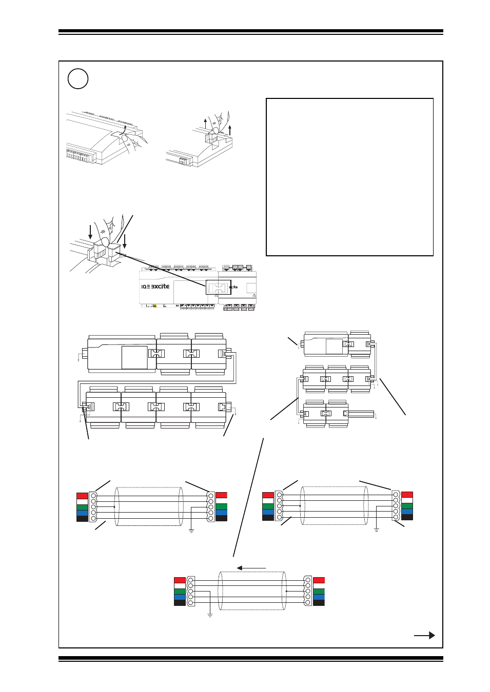
3 Installation - Mounting
(continued)
4 5 6
2
7 8 9
3
10 11 12
4
13 14 15
5
16 17 18
6
19 20 21
7
22 23 24
8
25 26 27
9
28 29 30
10
+ 0
+ 0
+ 0
+ 0
+ 0 + 0
+ 0
+ 0
+ 0
1 2 3
1
+ 0
0 V
24 V
24 V
34 35 36
12
37 38 39
13
40 41 42
14
A
31 32 33
P
11
43 44 45
15
46 47 48
16
100-240 V
OK RX
P 0 P 0
P 0
P 0 P 0
P 0
24
V
P 13 14 15
5
P 0
16 17 18
6
P 0
19 20 21
7
P 0
22 23 24
8
P 0
1 2 3
1
+ 0
4 5 6
2
+ 0
7 8 9
3
+ 0
10 11 12
4
+ 0
c
either use XCITE/IC interconnector (supplied with I/O module)
or wire special cable using XCITE/CC connectors and Belden 3084A cable
+24 Vdc
0 V
Data Hi
Data Lo
+24 Vdc
0 V
Data Hi
Data Lo
Ground
Ground
Red
White
Blue
Black
1
2
3
4
5
5
4
3
2
1
XCITE/CC connectors
Order separately (XCITE/CC/10, pack of 10)
Connect I/O Bus
(IQ3XCITE/96/.. and /128.. only)
if required
13
• A maximum of 15 I/O modules can be
connected.
• A maximum of 96 or 128 points (16 points in
the IQ3xcite and 80 or 112 expansion points)
can be used.
• The controller and its I/O modules are to be
fitted inside enclosures.
• No spurs are allowed on the I/O bus.
• If a single earth (ground) screened and bonded
contiguous metal enclosure is used, then
total I/O bus length can be up to 30 m (includes
use of multisection panels e.g. Form 4 enclosures)
If any other type of enclosure is used, or I/O
bus runs between enclosures, then total I/O
bus cable length can be up to 10 m.
(For cable length calculation, rigid interconnectors
can be ignored)
•Multiple enclosures must be earthed
(grounded) to a common earth (ground) point
(according to latest IEE Regs).
a
Open Flap
Belden 3084A cable
+24 Vdc
0 V
Data Hi
Data Lo
+24 Vdc
0 V
Data Hi
Data Lo
Ground
Ground
Red
White
Blue
Black
1
2
3
4
5
1
2
3
4
5
cable type A
cable type A
cable type B (right to right)
cable type B
(right to right)
Belden 3084A cable
Step 13 continued
XCITE/IC interconnector (supplied)
(XCITE/IC/5, pack of 5 available separately)
XCITE/CC connectors
Order separately (XCITE/CC/10, pack of 10)
connector rotated
through 180 °
+24 Vdc
0 V
Data Hi
Data Lo
+24 Vdc
0 V
Data Hi
Data Lo
Ground
Ground
Red
White
Blue
Black
5
4
3
2
1
5
4
3
2
1
Signal direction
cable type B (left to left)
cable type B
(left to left)
DIN rails must be
earthed (grounded)
DIN rails must
be earthed
(grounded)
b
Remove Terminator