Connect inputs (channels 1 to 10), Vi i t d, Segregate screen earth (ground) – TREND IQ3xcite User Manual
Page 3: Connect outputs (channels 11 to 16), Continued), 14 to 20 awg), cu only, 0 (0 v) n (in) + (+24v) n
3
IQ3xcite Web Enabled Controller Installation Instructions TG200626 Issue 2 21/04/08
Installation Instructions
IQ3xcite
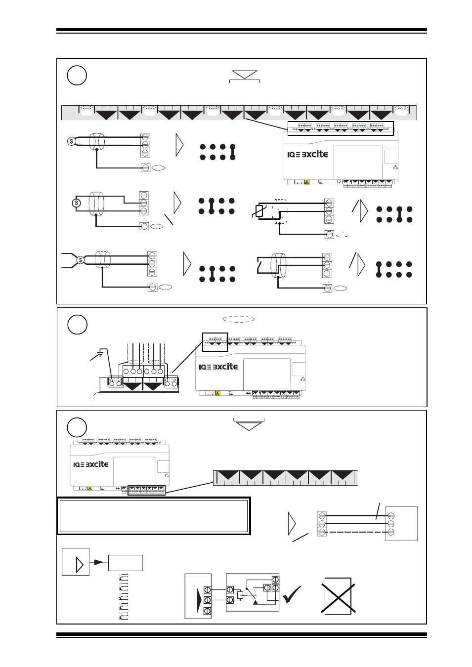
3 Installation - Mounting
(continued)
Connect Inputs (channels 1 to 10)
6
4 5 6
2
7 8 9
3
10 11 12
4
13 14 15
5
16 17 18
6
19 20 21
7
22 23 24
8
25 26 27
9
28 29 30
10
+ 0
+ 0
+ 0
+ 0
+ 0 + 0
+ 0
+ 0
+ 0
1 2 3
1
+ 0
0 V
24 V
24 V
34 35 36
12
37 38 39
13
40 41 42
14
A
31 32 33
P
11
43 44 45
15
46 47 48
16
100-240 V
OK RX
P 0 P 0
P 0
P 0 P 0
P 0
TP/1/1/22/HF/200 (Belden 8761) cable recommended for all inputs. Cable size 0.5 to 2.5 mm
2
(14 to 20 AWG), Cu only
4 5 6
2
7 8 9
3
10 11 12
4
13 14 15
5
16 17 18
6
19 20 21
7
22 23 24
8
25 26 27
9
28 29 30
10
+ 0
+ 0
+ 0
+ 0
+ 0 + 0
+ 0
+ 0
+ 0
1 2 3
1
+ 0
0 (0 V)
N (in)
+ (+24V)
N
Current input (external powered)
Thermistor input
linking
0V
0 (0 V)
N (in)
+ (+24V)
N
V (0 to 10V)
0 (0 V)
N (in)
+ (+24V)
N
Voltage input
Current input (loop powered)
SIG
® 1 (0 to 20 mA)
0 (0 V)
N (in)
+ (+24V)
N
® 1 (0 to 20 mA)
0V
SIG
0 (0 V)
N (in)
+ (+24V)
N
linking
linking
Digital input
linking
linking
V
I
I
T
D
Note that setting input links is described in Installation Instructions - section 4 step 6
N
EN61010:2001 MEASUREMENT CATEGORY 1. Separate from 230 Vac input power supply by double or reinforced insulation
(20 to 36 V)
5 V supply
5 V bridge supply
4 5 6
2
+ 0
1 2 3
1
+ 0
Segregate Screen Earth (Ground)
7
4 5 6
2
7 8 9
3
10 11 12
4
13 14 15
5
16 17 18
6
19 20 21
7
22 23 24
8
25 26 27
9
28 29 30
10
+ 0
+ 0
+ 0
+ 0
+ 0 + 0
+ 0
+ 0
+ 0
1 2 3
1
+ 0
0 V
24 V
24 V
34 35 36
12
37 38 39
13
40 41 42
14
A
31 32 33
P
11
43 44 45
15
46 47 48
16
100-240 V
OK RX
P 0 P 0
P 0
P 0 P 0
P 0
if required to segregate screen earth (ground) from controller input power supply earth (ground)
Note that screen earth (ground) link must
be cut (see section 4 step 7)
separate
earth (ground)
connection
Connect Outputs (channels 11 to 16)
8
4 5 6
2
7 8 9
3
10 11 12
4
13 14 15
5
16 17 18
6
19 20 21
7
22 23 24
8
25 26 27
9
28 29 30
10
+ 0
+ 0
+ 0
+ 0
+ 0 + 0
+ 0
+ 0
+ 0
1 2 3
1
+ 0
0 V
24 V
24 V
34 35 36
12
37 38 39
13
40 41 42
14
A
31 32 33
P
11
43 44 45
15
46 47 48
16
100-240 V
OK RX
P 0 P 0
P 0
P 0 P 0
P 0
N
34 35 36
12
37 38 39
13
40 41 42
14
31 32 33
11
43 44 45
15
46 47 48
16
P 0 P 0
P 0
P 0
P 0
P 0
TP/1/1/22/HF/200 (Belden 8761) cable recommended for voltage outputs
0
(out) N
P
N
LOAD
(0 V)
(+24 V)
optional
(0 to 10 Vdc, <=20 mA)
IQ3
Relay
Module
SRMV =
x 1
2SRM =
x 2
3RM =
x 3
6RM =
x 6
2RM =
x 2
nRM
N
Additional Relay Modules
(R/L, H/L)
(HCM/TRM)
If P terminal used, P input terminal must be
connected as in step 9 below
EN61010:2001 MEASUREMENT CATEGORY 1. Separate from 230 Vac input power
supply by double or reinforced insulation
Cable size 0.5 to 2.5 mm
2
(14 to 20 AWG), Cu only
I<=20 mA
If screened cable is used, terminate screen to earth (ground) at one end
e.g.
IQ3
SRMV
P
0
SRMAC
Analogue
outputs are
not suitable
for ac
relays
WARNING
If external supply is used to supply P input terminal, note whether
P bus is 24 Vac or 24 Vdc and only connect appropriate
output devices to P output terminals