Teledyne LeCroy QPHY-ENET User Manual
Page 48
48
QPHY-ENET Operator’s Manual Rev G
1000Base-T Peak Differential Voltage, Droop, Template - Mode 1 with Disturbing Signal
This test is defined in 40.6.1.2.1 as: The absolute value of the peak of the waveform at point A and B, as defined
in
X
Figure 35
X
, shall fall within the range of 0.67V to 0.82 V (0.75 V +/-0.83 dB). These measurements are to be
made for each pair while operating in test mode 1 and observing the differential signal output at the MDI using the
transmitter test fixture with no intervening cable.
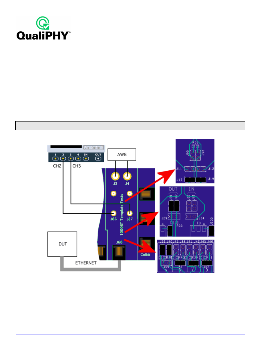
This test is performed on a physical interface transmitting the mode 1 waveform. Test section D is used to
perform the peak voltage and template tests. The disturbing sine wave is required for these tests. If you test mode
1 and 4 without disturbing sine wave, please refer to the
X
Mode 1 and Mode 4 without Disturbing Signal
X
topic
on page
X
54
X
. When a disturbing signal is not used, the measurement should be made with the device terminated
into a 100 Ω resistive load. The difference of the peak absolute value at the points A and B should be less than
1 %. Ideally, the peak voltage at points C and D is 0.5 times the average of the peak voltage at points A and B.
The absolute value of the peak voltage at point C and D difference should be less than 2 % from the ideal voltage.
Note: The method for putting a particular PHY device into this and the other test modes required for 1000Base-T tests is unique to the
manufacturer. Contact the manufacturer of your PHY device for information on how to do this.
Figure 36. Fixture setup for Mode 1 and Mode 4 test with Disturbing Signal