Teledyne LeCroy QPHY-ENET User Manual
Page 34
34
QPHY-ENET Operator’s Manual Rev G
10-Base-T Output Timing Jitter
The timing jitter at the output of the MAU is determined by measuring the timing of the zero crossings at 8 bits and
8.5 bits from the triggering zero crossing. The jitter is measured and reported in parameter P1 below the grid on
the oscilloscope display.
A random bit stream from the device is used for this test, and two jitter measurements are made: one on the
transition at 8 bits from the trigger and the other at the transition at 8.5 bits from the trigger. The transitions
represent TD1 and TD0 values and are indicated in the user interface as 8 BT and 8.5 BT, respectively. In either
case (TD1 or TD0) the jitter, as indicated in parameter P1, shall be less than 22 ns for an internal MAU and 11 ns
for an external MAU. The output jitter is measured with and without the Twisted Pair Model and terminated into a
100 Ω resistive load.
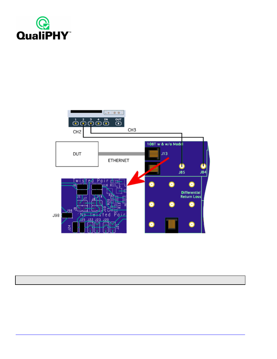
Figure 24. Fixture setup for jitter test
1. Connect DUT to J13 at section A of TF-ENET-B by using a short RJ45 cable included with TF-ENET-B
package. Install jumpers for the test with TPM 100 Ω. Refer to
X
Table 2
X
(previous).
2. Connect oscilloscope channel 2 to J84, channel 3 to J85 (
X
Figure 24
X
).
3. Set the DUT to transmit Pseudo-Random bit stream.
Note: The DUT can be set to transmit random data by connecting the DUT to a Link Partner and transmitting a large file to the partner.
Please see the Link Partner Testing For 10BASE-T & 100BASE-TX Devices section of this manual for details on using a Link Partner.
4. Touch the 10Base-T button under “Select Standard.”
5. Select Output Timing Jitter 8 BT in the “Select Test” field.
6. Select external or integrated MAU as appropriate in the “MAU Type” field.
7. Touch the Set Up and Start Test button to begin testing.
8. The measurement displayed in P1 is the peak-to-peak value of the variation in the location of the
transition.