Eye diagram and mask test setup detail, Input signal setup, Mask test setup – Teledyne LeCroy FlexRay Trigger, Decode and Physical Layer Test User Manual
Page 19
O
PERATOR
’
S
M
ANUAL
Eye Diagram and Mask Test Setup Detail
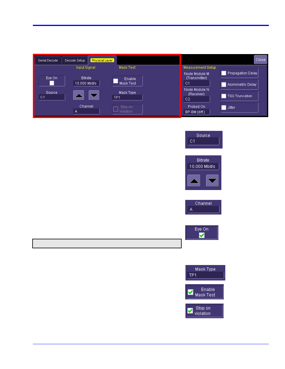
The Left Hand side of the FlexRay Physical Layer tab has all the settings for Eye Diagram Mask testing as seen
below.
settings for Eye Diagram Mask testing as seen
below.
Input Signal Setup
Source – The pop-up dialog is used to select the channel, math or
memory waveform to use for the eye diagram creation
Bitrate – The eye diagram can be created from FlexRay waveforms
with bitrates of 2.5 Mb/s, 5 Mb/s and 10 Mb/s as defined in the FlexRay
specification. The value can be entered by using the arrow keys or
touching the field and entering a value.
Channel – Select the appropriate FlexRay channel if the signal being
used for the eye diagram is from Channel A or Channel B of the
FlexRay bus.
Eye On/Off – Toggle this button on and off to turn the eye diagram on
and off
Note: The time required to build an eye diagram of long memory waveforms is longer
than if short memory was used
Mask Test Setup
Mask Type – Select the desired mask for testing. Choices include TP1
and TP4, these are the only masks defined in the FlexRay
specifications
Mask Test On/Off – Toggle mask testing on and off to perform the
test. Mask violations appear with red failure indicators
Testing Action – Select the Stop on Action capability to stop the
oscilloscope from triggering once a failure occurs to understand where
the failure occurred.
FlexRay-TDP-OM-E Rev A
19