Teledyne LeCroy ZS4000 User Manual
Page 18
ZS4000 High-Impedance, Active Probe
12
923360-00 Rev A
Where C
total
is the combined probe and circuit capacitance and R
total
is combined
circuit and probe resistance.
For a setup where Ct = 0.6 pF and a source resistance is 250 Ω, the measured rise
time will be 330 ps, which will correspond to a bandwidth of 909 MHz, assuming
no inductive loads.
t
rise
= 2.2 x 0.6 x 10
-12
x 250 Ω = 330 ps
Parallel combination of 250 Ω and 1 MΩ is still 250 Ω
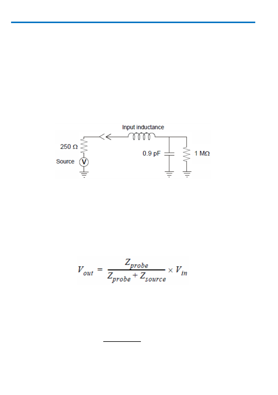
Probe input equivalent circuit
To illustrate the effect of capacitive loading at higher frequencies:
At a frequency of 750 MHz the reactance of the 0.6 pF capacitance is 354 Ω, and
at 1.0 GHz the reactance has been lowered to 265 Ω.
If, at a given frequency, the source impedance is large with respect to the input
impedance, a measurable reduction in the output signal amplitude may occur.
where Z
probe
is the probe’s input impedance and Z
source
is the source impedance.
For example: At 750 MHz, where the probe input impedance has reduced to 354
Ω, and a source resistance of 250 Ω the probe output amplitude is reduced to:
- 6Zi Rackmount (12 pages)
- HDO Oscilloscope Rackmount (14 pages)
- LSIB-1 Host Interfaces (44 pages)
- OC1021 Oscilloscope Cart (9 pages)
- OC1024 Oscilloscope Cart (10 pages)
- OC910 Oscilloscope Cart (2 pages)
- TTL-AUX-OUT (1 page)
- WaveJet Rackmount (1 page)
- Zi Oscilloscope Rackmount (12 pages)
- USB2-GPIB (12 pages)
- WM8Zi-2X80GS (2 pages)
- WR6ZI-8CH-SYNCH (6 pages)
- Zi Oscilloscope Synchronization ProBus Module (Zi-8CH-SYNCH) (16 pages)
- LogicStudio (42 pages)
- WaveSurfer MXs-B Getting Started Manual (126 pages)
- WaveSurfer MXs-B Quick Reference Guide (16 pages)
- X-STREAM OSCILLOSCOPES Remote Control (305 pages)
- WS-GPIB (12 pages)
- PXA125 (219 pages)
- PXD Series (42 pages)
- PXD222 (38 pages)
- Oscilloscope System Recovery (8 pages)
- LabMaster 9Zi-A (264 pages)
- LabMaster 10Zi Rackmount (8 pages)
- LabMaster 10Zi Getting Started Manual (236 pages)
- LabMaster 10Zi Operators Manual (198 pages)
- WaveAce 1000_2000 (108 pages)
- WaveAce 1000_2000 Remote Control (92 pages)
- WaveRunner Xi-A Quick Reference Guide (16 pages)
- WaveRunner XI SERIES Operator’s Manual (233 pages)
- WaveMaster Automation Command (667 pages)
- WaveMaster 8 Zi_Zi-A (190 pages)
- WaveMaster 8000A (46 pages)
- WavePro 7 Zi_Zi-A (188 pages)
- WaveExpert series Automation Manual (285 pages)
- WaveExpert 9000_NRO9000_SDA100G Getting Started Manual (50 pages)
- WaveExpert 100H Operators Manual (348 pages)
- WaveRunner Automation Command (460 pages)
- WaveRunner Xi-A Getting Started Manual (128 pages)
- WaveRunner 6 Zi and 12-Bit HRO Getting Started Manual (198 pages)
- WaveRunner 6 Zi Quick Reference Guide (20 pages)
- WaveRunner 6 Zi-ExtRef-IN_OUT (2 pages)
- WaveSurfer Automation Command (226 pages)
- HDO 4000 Getting Started Guide (48 pages)
- HDO Removable Hard Drive (2 pages)