Operation with a teledyne lecroy oscilloscope, Connecting the probe to the test circuit – Teledyne LeCroy ZS4000 User Manual
Page 15
Operator’s Manual
923360-00 Rev A
9
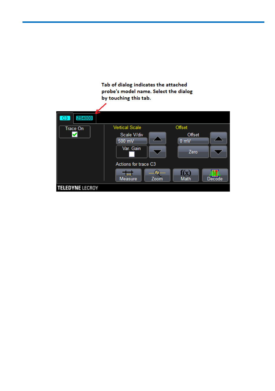
Operation with a Teledyne LeCroy Oscilloscope
When the ZS4000 probe is connected to any compatible Teledyne LeCroy
oscilloscope, the displayed scale factor and measurement values are
automatically adjusted. A Probe dialog appears behind the corresponding
Channel dialog.
The probe can be controlled through the oscilloscope user interface:
The Volts/Div knob controls the oscilloscope’s scale factor to give full
available dynamic range up to 2 V/div (16 V peak to peak).
The channel Offset knob controls the probe input offset circuit over its
range of ±12 V.
Refer to your oscilloscope’s manual for specific operation instructions.
Connecting the Probe to the Test Circuit
To maintain the high performance capability of the probe in measurement
applications, care must be exercised in connecting the probe to the test circuit.
Increasing the parasitic capacitance or inductance in the input paths may
introduce a “ring” or slow the rise time of fast signals. Input leads which form a
large loop area will pick up any radiated electromagnetic field which passes
through the loop and may induce noise into the probe input.
Using one of the available accessories makes the ZS2500 probe with its small
profile and low mass head ideally suited for applications in dense circuitry.