Preliminary procedure, Procedure – Teledyne LeCroy HFP1500 User Manual
Page 38
HFP1500 High Frequency Probe
32
922252-00 Rev
A
Preliminary Procedure
1. Remove the two screws that secure the plastic cover on the cable end of the ProBus
interface housing.
2. Gently pull on the probe cable to slide the circuit board assembly from the metal
housing.
3. Connect the HFP1500 probe to the female end of the ProBus extension cable, being
careful to line up all six pins of the probe connector. Connect the male end of the
ProBus extension cable to channel 1 of the oscilloscope.
4. Apply power to the oscilloscope and test equipment.
5. Allow at least 30 minutes warm-up time for the HFP1500 and test equipment before
starting the calibration procedure.
Procedure
Adjust Output Zero
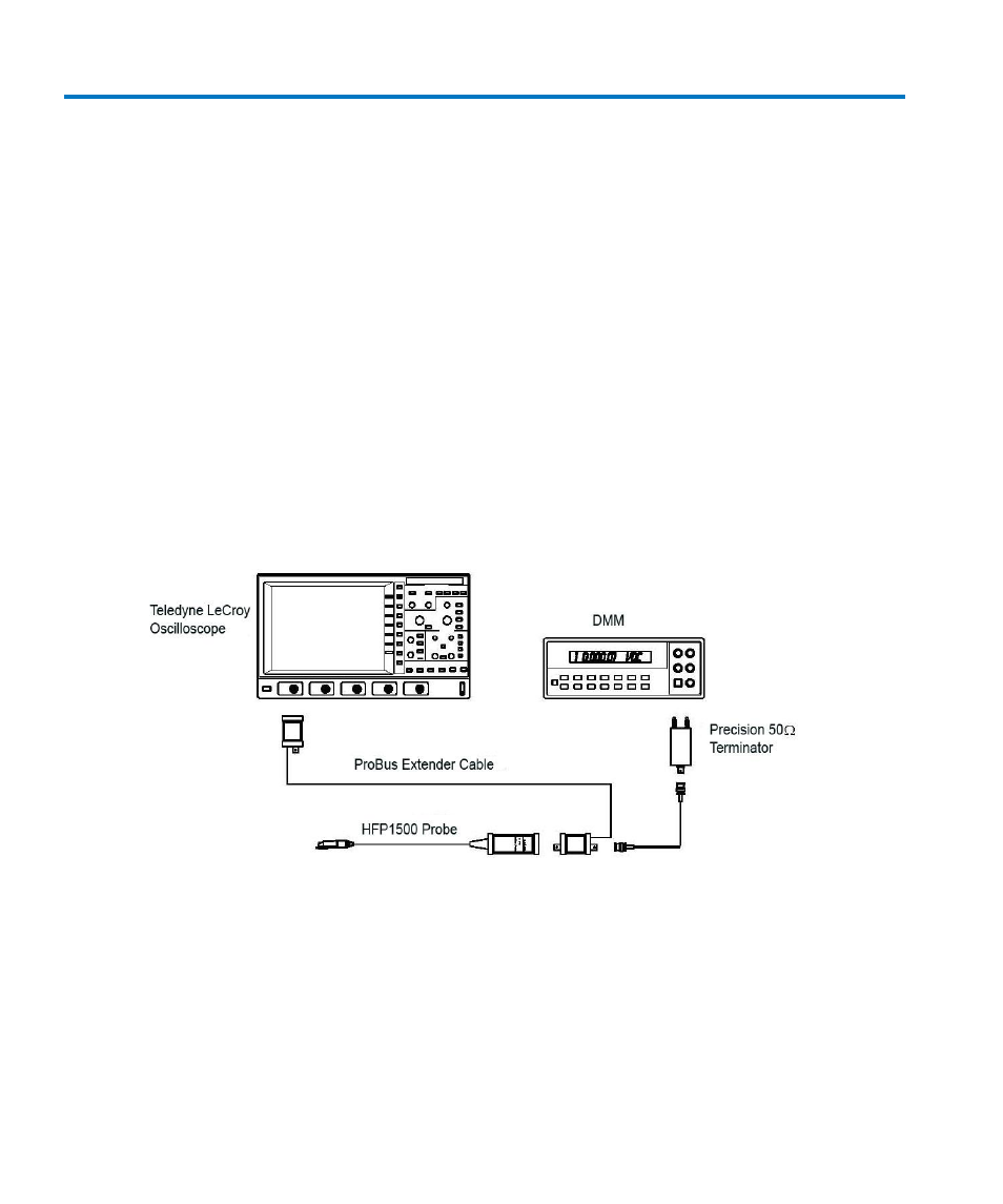
Figure 7 Output Zero Voltage Adjustment Setup
1. Connect one end of a BNC cable to the probe end of the ProBus extension cable. Connect
the Precision 50 Ω Terminator to the other end of the BNC cable.
2. Connect the banana plugs of the precision 50 Ω terminator to the input of the DMM. Make
sure the plug corresponding to the BNC shield (marked ’Ground’) is connected to the LO or
COMMON input of the DMM. Refer to Figure 7 Output Zero Voltage Adjustment Setup for
setup information.