Teledyne LeCroy HFP1500 User Manual
Page 32
HFP1500 High Frequency Probe
26
922252-00 Rev
A
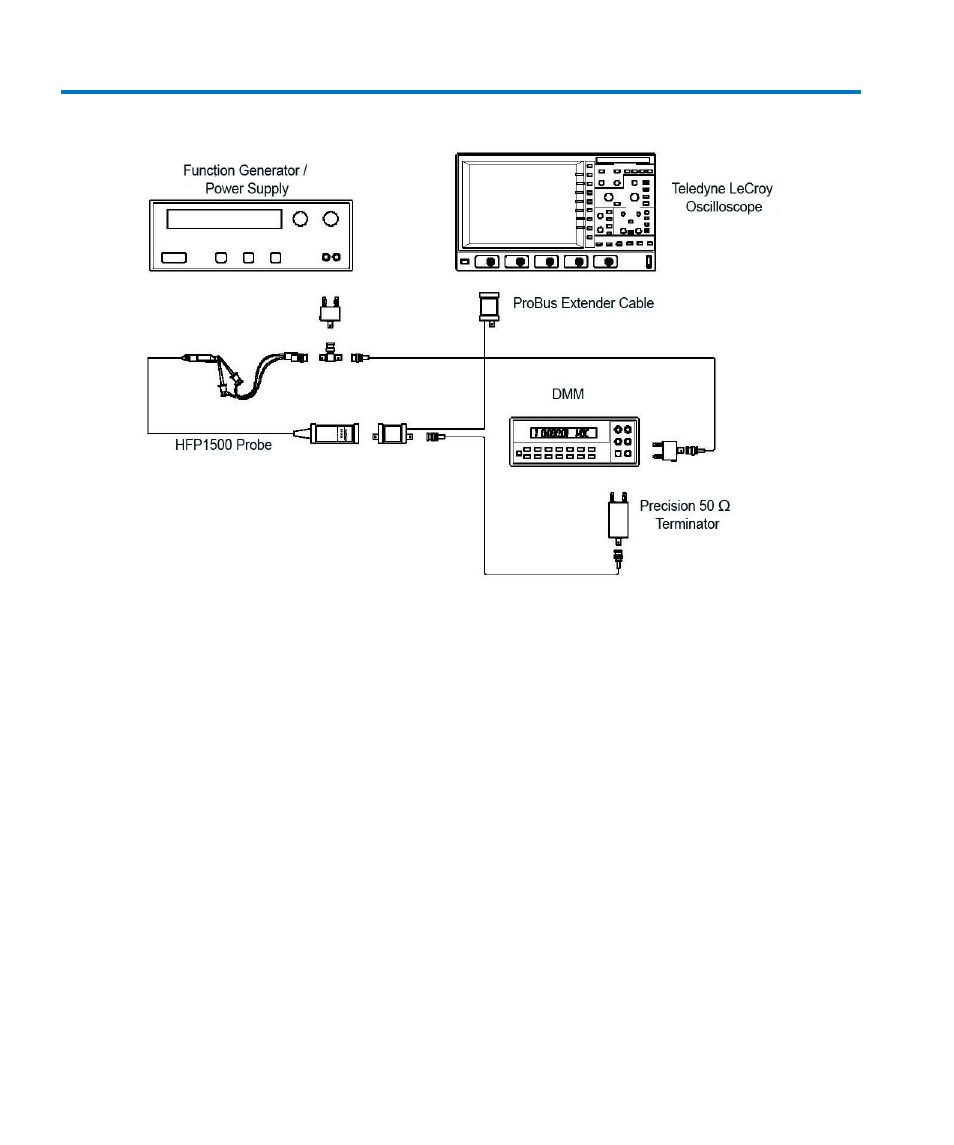
B. LF Attenuation Accuracy
Figure 6 Attenuation Accuracy Test Setup
1. Connect the BNC end of the BNC to mini-grabber cable to a female end of the BNC tee
adapter. (Refer to Figure 6
Attenuation Accuracy Test Setup
2. Carefully insert the Straight Tips (supplied in accessory kit) into the sockets of the probe
head. Attach the red lead of the mini-grabber to the signal input and the black lead to the
ground input of the probe head.
3. Set the power supply to approximately 0 Volt.
4. Plug the dual banana plug adapter with probe attached into the output terminals of the
power supply with ground side of the adapter (and the ground side of the probe head)
connected to the positive terminal of the power supply.
5. Attach a BNC cable to the unused female port of the BNC tee and a dual banana plug
adapter to the other end of the cable and plug the dual banana plug adapter into the DMM
input. Make sure the side of the banana plug adapter corresponding to the BNC shield
(marked "GROUND") is connected to the LOW or COMMON input of the DMM.
6. Adjust the power supply to an output of 10.0 V ± 100 mV as indicated on the DMM.