Pxd series digitizer – Teledyne LeCroy PXD Series User Manual
Page 36
32
ISSUED: March 2003
901217-01
PXD Series Digitizer
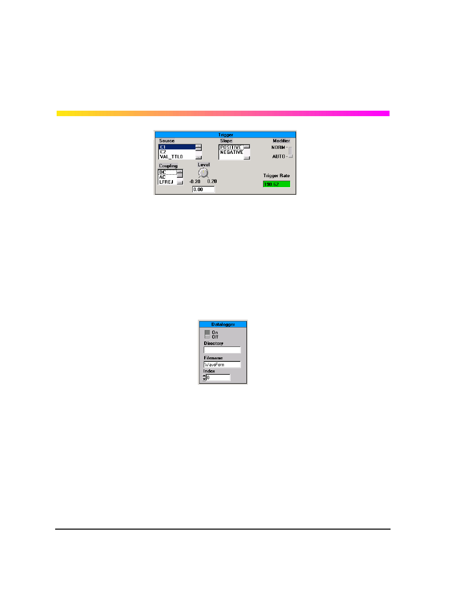
Source: The trigger source for the digitizer may be either of the input channels or the PXI Trigger
and Star Trigger lines on the PXI backplane.
Coupling: This sets the trigger coupling for the input channels. DC is used when all the signal
components (AC and DC) are coupled to the trigger circuit. When AC is selected, the signal is
capacitively coupled, DC levels are rejected, and frequencies below 50 Hz are attenuated.
Level: Defines the source voltage at which the trigger circuit will generate an event.
Slope: Determines the direction of the trigger voltage transition used to generate a particular trig-
ger event.
Modifier: In NORM mode the digitizer will acquire while there is a valid trigger. In AUTO mode the
trace will automatically be displayed regardless of a valid trigger. When a valid trigger is present in
Auto mode, the Digitizer will behave as if in Normal mode.
On/off: Turns datalogging on and off.
Directory: Sets the directory for storing waveforms. Entering a period sets the current directory of
the Quick-Start Demo; entering another value (e.g., "Test 1") creates a new folder called "Test1"
referenced from the current directory.
Filename: Sets prefix for the filename.
Index: An auto-incrementing index is appended to the filename. When the datalogger is turned on,
and the program is in Continuous Acquisition mode, each waveform will be stored.
USING THE PXD SERIES DIGITIZER IVI INSTRUMENT DRIVERS
The CD-ROM includes several example programs written in LabWindows/CVI using the PXD
Series IVI driver. Even if you are not using CVI, the ".c" files provide practical examples that will
help you learn how to program the Digitizer.
§ § §