Operation – Teledyne LeCroy PXD Series User Manual
Page 35
Operation
901217-01
ISSUED: March 2003
31
Offset CH1 and CH2: Set the Offset for each input independently using the Offset knob or by typ-
ing a value in the Offset field. The Offset knob will change color depending on the channel
selected: yellow when channel 1 is selected and red when channel 2 is selected. These colors
also match the trace colors in the graphics display.
Bandwidth Limit CH1 and CH2: To suppress high frequency noise on waveforms, limit the band-
width of the digitizer by selecting a 20 MHz or 200 MHz filter. This function smooths the displayed
waveform by blocking frequencies above the filter’s limit.
Coupling CH1 and CH2: Each channel of the digitizer is set to DC coupling by default so that AC
and DC signals appear on the display. Select AC coupling (in the Trigger control section) to view
the AC signal only. Clicking the switch control toggles the selection.
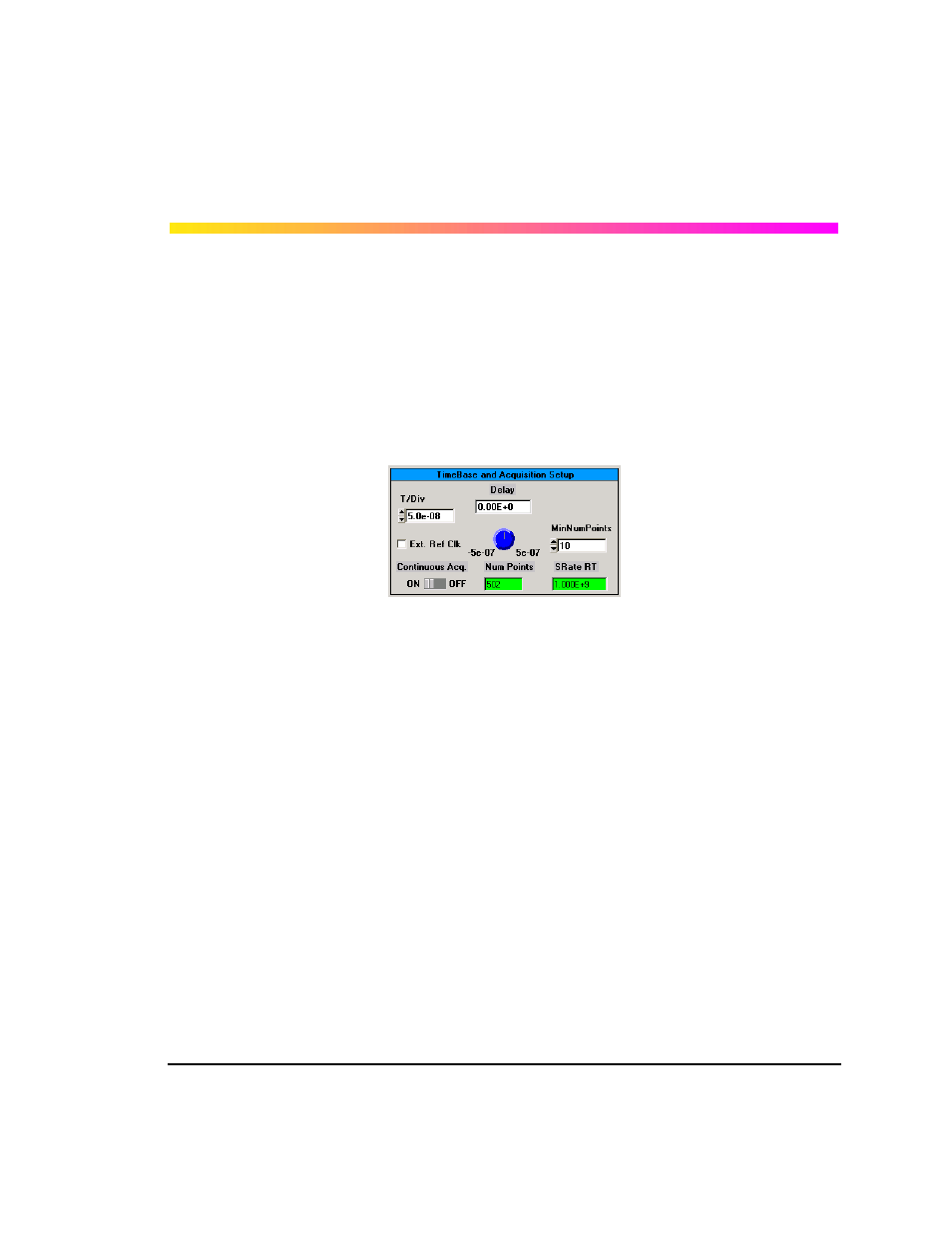
T/Div: The time per division is set by using the T/Div arrows or by selecting a value from the T/Div
field. The Digitizer automatically adapts itself to use the maximum sampling rate whenever the
timebase is changed.
Delay: Turn the Delay knob to adjust the horizontal position and the amount of pre-trigger, as
desired.
Number of Points: This is an indicator that displays the number of points in each acquisition. This
will vary automatically depending on the T/Div.
Sample Rate: This is an indicator that displays the sample rate for each acquisition. This will vary
automatically depending on the T/Div.