3 output circuits, Output circuits – System Sensor PDRP-2001 User Manual
Page 95
PDRP-2001 Series Manual — P/N 53043:E1 2/28/2011
95
Read Status
Operating Instructions
The operator selects the zone which is to be viewed by pressing the number corresponding to the
desired zone in each screen. For example, if 1 is pressed in the first screen, the display will change
to a screen similar to the following:
Pressing the down arrow key, while viewing the screen shown above, will allow the operator to
view additional programming information about the selected device, such as:
•
Enable/Disable Status
•
Device Type
•
Output Circuit MAP
•
Adjective/Noun descriptor
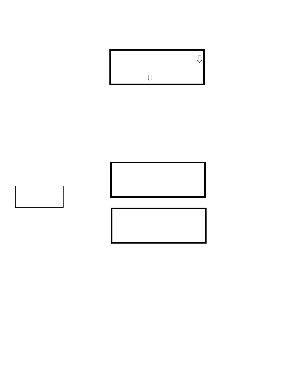
4.15.3 Output Circuits
Pressing 3 while viewing Read Status Screen #1 will display the following screens:
The operator can press 1 to view the programmed options for Output 1, 2 to view the programmed
options for Output 2, 3 to view the programmed options for Output 3, or 4 to view the programmed
options for Output 4.
The resulting screens will display the following information:
•
Enable/Disable Status
•
Circuit Type
•
Silenceable/Nonsilenceable
•
Auto Silence Enable/Disable and time delay (in minutes)
•
Silence Inhibit Enabled/Disabled
•
Coding Selection (Temporal, Steady, etc.)
READ INPUT ZONE 1
NORMAL PULL STATION
PRESS TO VIEW
READ STATUS
1=FACP CONFIG
2=INPUT ZONES
3=OUTPUT CIRCUITS
Read Status Screen #1
READ OUTPUTS
1=OUTPUT 1
2=OUTPUT 2
3=OUTPUT 3
READ OUTPUTS
1=OUTPUT 4
Read Outputs Screen #2
Read Outputs Screen #1