In-duct sampling, Design considerations for in-duct sampling, Small duct sampling – System Sensor Pipe Installation User Manual
Page 17
User Guide: Aspirating Smoke Detector Pipe Installation
17
In-Duct Sampling
The FAAST detector is approved for in duct applications.
National and local safety standards and codes recognize the
ability of air duct systems to transfer smoke, toxic gases, and
flame from area to area. Sometimes smoke can be of such
quantity as to be a serious hazard to life safety unless blowers
are shut down and dampers are actuated. The primary purpose
of duct smoke detection is to prevent injury, panic, and property
damage by reducing the spread (recirculation) of smoke.
Duct smoke detection also can serve to protect the air
conditioning system from fire and smoke damage, and can
be used to assist in equipment protection applications, for
example, in the ventilation/exhaust duct work of mainframe
computers and tape drives. For additional information relating
to duct applications, refer to the duct application white paper
at systemsensor.com/faast.
Design Considerations for In-Duct Sampling
The following guidelines are necessary to obtain the best
installation results.
1. Pipes should always be supported at both duct walls –
rubber grommets can be used. Silicon sealer must also
be used to ensure an airtight seal in the duct walls.
2. Inlet pipes must be inserted between six and ten
duct widths or diameters (for round ducts) from any
disturbances to the flow generated by sharp bends,
plenums, nozzles, branch connections, etc…
3. Sampling ports should be located no closer than 2” to
the duct wall.
4. Ports on the inlet pipe should face 20-45 degrees into the
air flow with the ports concentrated at the center of the
duct as shown in figure 22.
5. The exhaust pipe must have 4, 3/8" (9.5 mm) ports. Ports
should be concentrated in the middle of the duct’s width
and spaced evenly. Ports on the exhaust pipe should be
oriented such that they face away from the air flow.
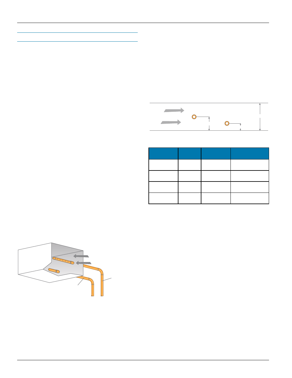
Small Duct Sampling
For ducts with a width less than 3 ft. (1 m), the inlet pipe should
be installed at the midpoint of the duct height or diameter.
Exhaust pipes should be inserted at 18" (0.5 m) downstream
from the input pipe. The exhaust pipe should be at one quarter
of the duct height or diameter, as shown in figure 23. To avoid
dilution, sampling pipes should be located before fresh air
intakes and before the exhaust air output.
Figure 23: Design considerations for in-duct sampling.
Figure 24: Small duct sampling.
Direction of
Air Flow
Air Supply to
FAAST Device
Exhaust Pipe from
FAAST Device
Inlet Pipe
H/2
Outlet Pipe
H
H/4
Air Flow
Small Diameter Duct
Duct Width
Number
of Ports
Port Size
Nominal Pipe
Flow Rate (CFM)
12 in.
(300 mm)
2
1/4 in.
(6.5 mm)
1.84 cfm
(52.0 L/min)
20 in.
(500 mm)
3
1/4 in.
(6.5 mm)
1.83 cfm
(51.9 L/min)
28 in.
(700 mm)
4
11/64 in.
(4.5 mm)
1.70 cfm
(48.1 L/min)
36 in.
(900 mm)
5
5/32 in.
(4 mm)
1.81 cfm
(51.2 L/min)
Table 4: Port sizes for small ducts.