High air exchange areas – System Sensor Pipe Installation User Manual
Page 16
User Guide: Aspirating Smoke Detector Pipe Installation
16
Generally the FAAST detector should not monitor more than
two air handling units. When monitoring multiple units with one
device, the AHUs should have similar flow at all times. The
number of air handlers monitored is limited by the maximum
length of the pipe network. However, the degree of particle
dilution and air movement that occurs with multiple air handlers
can adversely affect system response times. Final system
testing should be done to confirm actual response times.
High Air Exchange Areas
Typically, high air exchange areas have some form of
mechanical ventilation to maintain constant or cyclical air
flow for heating, cooling or maintaining some other sort of
special environment. Smoke tends to travel with the air flow, so
positioning sampling pipes near the return of an air handling
unit or heating/air conditioning unit ensures early detection of
particulate in the area.
Normal sampling methods for high air exchange areas are a
combination of return air and ceiling sampling. The return air
sampling provides protection when the air flow is present. The
ceiling network provides protection when the air flow is off.
Local codes typically require smaller sample areas (closer
spacing of sample ports) as the air flow rate increases.
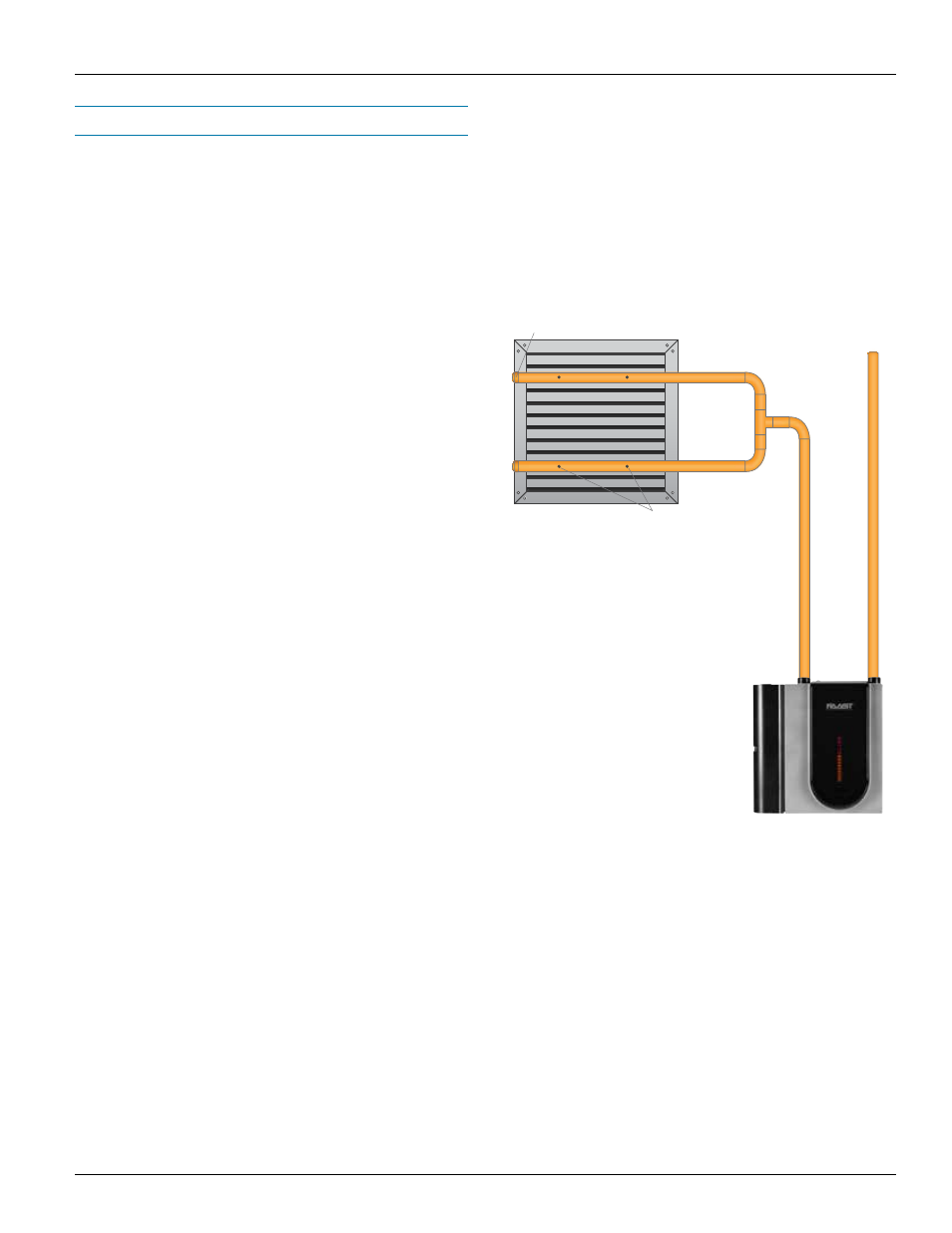
Return Air Sampling
Return air sampling provides an effective means of Very Early
Warning in a high air velocity environment. Placing the pipe
network sampling ports directly in the air stream at a return
air grill allows the system to monitor air that has circulated
throughout the protected area.
The following guidelines should be reviewed and followed to
ensure proper sampling by the detector system:
1. More than one sampling location may be required for large
air grills. NFPA 76 recommendations specify that each
sampling port can cover a maximum of 4 sq. ft. (0.4 m
2
)
2. Sampling ports should be aligned at an angle of 20 to 45
degrees to the direction of the maximum air flow.
3. Sampling pipes should be placed in the path of the
greatest air flow.
4. The number of bends in the pipe network should be kept
to a minimum.
5. Pipe ends should be capped with an end cap. Depending
on the pipe design and PipeIQ recommendations, the end
caps may or may not have a sampling port.
6. Socket unions should be used in locations where the pipe
network requires the removal of the pipes on a regular
basis for maintenance purposes.
7. Use of standoff fittings to keep the pipe network at least 2"
to 8" (50 mm to 200 mm) in front of the grill for high velocity
air flow locations. Installing the network any closer to the
input grill locates the sample port in an area of negative air
pressure.
8. Always keep in mind that the monitored environment
should still ensure coverage even if the manufactured air
flow gets disrupted.
Figure 22: Return air sampling.
End cap
4ft. x 4ft.
Intake
Sample Ports
• NFPA calls for 4 sq. ft. max
per sample port
• Pipes to be positioned on 2-8"
stand-offs from grill opening
• Ports to be positioned 20" - 45"
into the direction of air flow