Operation test, Fig ) – Superwinch Certus Wireless for Superwinch S Series winches User Manual
Page 8
8
29
After mounting and wiring is complete, test the operation of the system to be
sure the drive is operating in the proper direction utilizing the operation switch
on the control unit. Should it be operating in reverse, swap the two motor wires
on the unit and re-test. Then test transmitter to verify operation.
OPERATION TEST
1. Turn on the supply voltage to the receiver.
2. Press the start button and the operation LED flashes once. see (Fig. 2).
3. Check to see if the operation of the transmitter corresponds to the operation
of the machinery.
4. Check the stop function. After pressing the stop button, the machine should
not be able to be controlled by the transmitter.
5. If the checks are finished and everything is functional, the system is
operational
heck to ensure that the ground and positive leads from
he battery are disconnected before performing any
electrical work.
WARNING
!
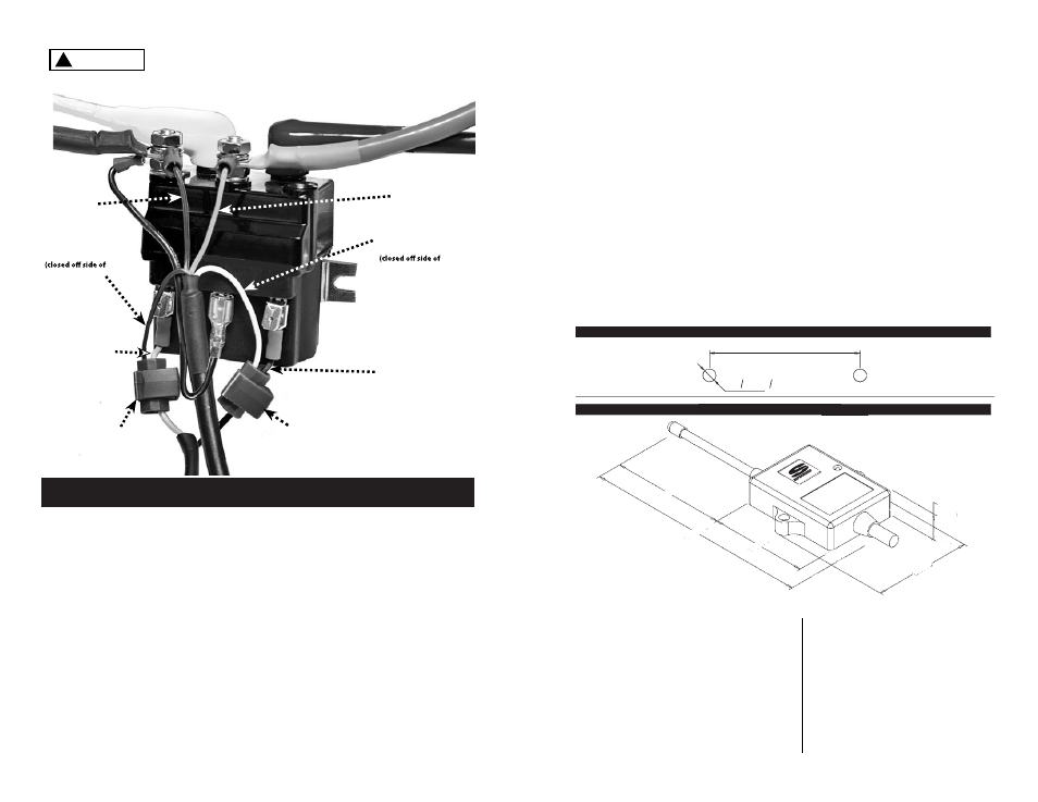
(Fig )
BLACK Wire
from
Harness
Assembly
RED Wire
from
Harness
Assembly
GREEN Wire from
handle bar switch
(green wire passes
through connector)
Splice Connector
Splice Connector
YELLOW Wire from
Harness Assembly
connector used)
BLACK Wire from
handle bar switch
(black
wire passes
through connector)
BLUE Wire from
Harness Assembly
connector used)
. 4
C
t
El transmisor tiene 2 LED (véase Fig. 2). El LED 1 es rojo e indica baja carga
de pilas (véase la página 3). El LED 2 es verde e indica que hay transmisión y
funcionamiento. Parpadea al pulsar cualquier botón de funcionamiento para
mostrar que la señal se transmite al receptor. El transmisor tiene un botón verde
(arranque), un botón rojo (parada) y dos botones negros (enrollar y desenrollar
el cable). Al oprimir el botón de parada se anulan todos los relés/interruptores
del receptor. El botón de parada tiene prioridad, por lo cual prevalecerá aunque
esté oprimido cualquier otro botón. Si la unidad permanece activa al menos por
dos minutos o se ha pulsado el botón de parada, el sistema se apagará. Tendrá
que activarse antes de volver a usarlo. Para activar el sistema pulse el botón
verde de arranque. El LED verde se encenderá una vez. El sistema está listo para
usarse.
El transmisor está ahora programado y listo para usarse.
3.78”(96mm)
7.48”(190mm)
3.23”(82mm)
3.27”(83mm)
.
87”(22mm)
2.78” (70.5mm)
2x O.236” (O6mm)
DIMENSIÓN DREILLING TEMOLATE
DIMENSIÓN DEL RECEPTOR