Ss actuator, Installation – IAI America SSCR User Manual
Page 9
Page 7
SS Actuator
7. Installation
We'll describe the installation process using a single axis unit.
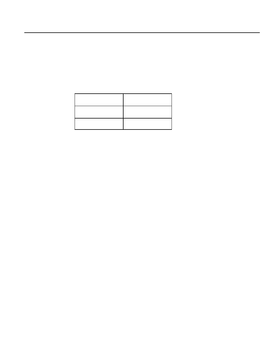
There are tapped holes for mounting on the back side of the actuator. The tap effective length for
base mounting is indicated in the table below. Please make sure that the bolt tip does not overhang.
h
t
g
n
e
L
e
v
i
t
c
e
f
f
E
p
a
T
e
p
y
T
ll
a
m
S
S
S
m
m
8
e
p
y
T
m
u
i
d
e
M
S
S
m
m
0
1
7.1 Attaching the Slider Carrying the Payload
7.2 Mounting Surface
• The mounting table should have sufficient rigidity to avoid generating vibration.
• The surface where the actuator will be mounted should be machined or be equally level and the flatness
• tolerance between the actuator and the table should be within 0.05mm.
• Provide enough space around the actuator to permit maintenance work to be done.
• The slider travelling plane is the reference plane for the actuator base and the lower surface. When travelling
• precision is required, use this as the reference plane for mounting.
• The mounting table should have sufficient rigidity to avoid generating vibration.
• The surface where the actuator will be mounted should be machined or be equally level and the flatness
tolerance between the actuator and the table should be within 0.05mm.
• Provide enough space around the actuator to permit maintenance work to be done.
• The slider travelling plane is the reference plane for the actuator base and the lower surface. When travelling
precision is required, use this as the reference plane for mounting.