Part 11, Shutdown, A. shutdown procedure – HTP PHR199-55C User Manual
Page 64: B. vacation procedure, C. failure to operate, Part 12, Troubleshooting, A. appliance error code, B. appliance error, C. appliance fault
64
LP- 325 REV. 3.21.14
PART 11 – SHUTDOWN
A. SHUTDOWN PROCEDURE
If the burner is not operating, disconnect the electrical supply.
If the burner is operating, lower the set point value to 70
o
F and wait for the burner to shut off. Continue to wait for the combustion
blower to stop, so all latent combustion gases are purged from the system. This should take a maximum of 40 to 90 seconds.
B. VACATION PROCEDURE
If there is danger of freezing, change the set point to 70
o
F. DO NOT turn off electrical power. If there is no danger of freezing, follow
“Shutdown Procedure”.
C. FAILURE TO OPERATE
Should the burner fail to light, the control will perform two more ignition trials prior to entering a lockout state. Note that each
subsequent ignition trial will not occur immediately. After a failed ignition trial, the blower must run for approximately 10 seconds to
purge the system. Therefore, a time period of approximately 40 to 90 seconds will expire between each ignition trial.
If the burner lights during any one of these three ignition trails, normal operation will resume. If the burner lights, but goes off in about 4
seconds, check the polarity of the wiring. See electrical connection section.
If the burner does not light after the third ignition trial, the control will enter a lockout state. This lockout state indicates that a problem
exists with the appliance, the controls, or the gas supply. Under such circumstances, a qualified service technician should be contacted
immediately to properly service the appliance and correct the problem. If a technician is not available, depressing the
{S4}
button once
will remove the lockout state so additional trials for ignition can be performed. The unit will try to re-light once every 6 minutes.
PART 12 – TROUBLESHOOTING
A. APPLIANCE ERROR CODE
An error code may occur in the installation of the appliance. This condition may lead to a lock out
condition of the controller, which will need to be manually reset through the
{S4}
button. These
temporary codes will help the installer correct the problem before going into a lock out condition,
which will require a manual reset.
B. APPLIANCE ERROR
1. When an error condition occurs the controller will display an error code on the display module.
2. These error codes and several suggested corrective actions are included in Table 17.
C. APPLIANCE FAULT
1. When a fault condition occurs the controller will illuminate the red “fault” indication light and
display a fault code in the format (Example:
|F00|
) on the display module.
2. Note the fault code and refer to Table 18 for an explanation of the fault code along with several
suggestions for corrective actions.
3. Press the reset key to clear the fault and resume operation. Be sure to observe the operation of
the unit to prevent a recurrence of the fault.
D. NO HOT WATER (DHW) (VERSA-FLAME)
1. Ensure the DHW pump is not air locked. Also, ensure the pump is directing flow in the correct
direction (arrow pointing towards the return port). Pressure in the tank must be a minimum of 8 psi.
2. Check the flow switch. Ensure that it is connected and installed properly (flow arrow pointing
towards the heat exchanger). Also, ensure the flow switch is properly wired to the appliance
(terminals 10 and 11 on the field connection board).
3. Adjust the low limit setting higher.
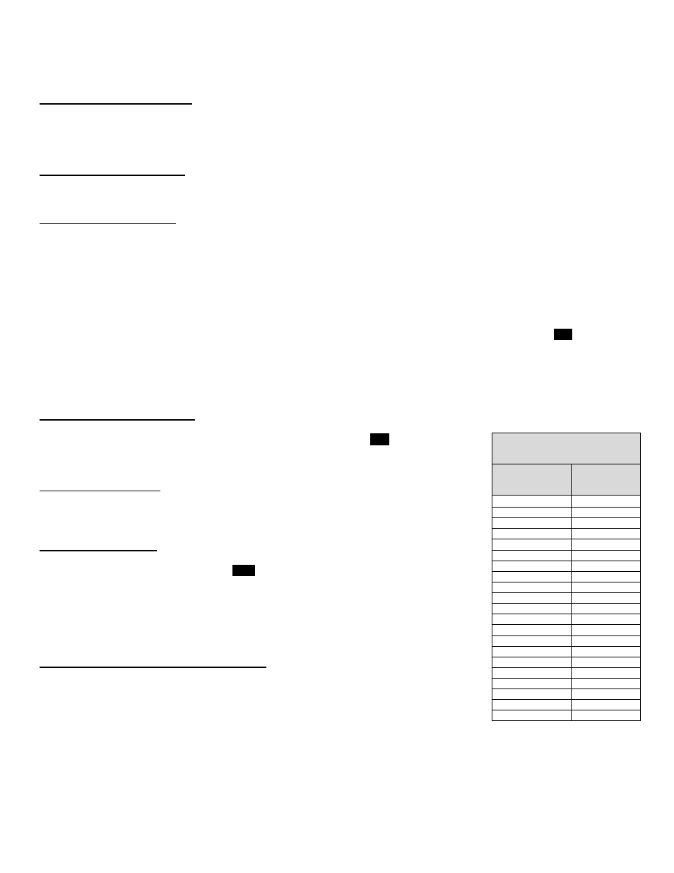
RESISTANCE TABLE FOR
SUPPLY TEMPERATURE
SENSOR
HIGH/LOW
TEMP. SENSOR
TEMP. (
o
F)
RESISTANCE
(ohms)
32
32550
41
25340
50
19870
59
15700
68
12490
77
10000
86
8059
95
6535
104
5330
113
4372
122
3605
131
2989
140
2490
149
2084
158
1753
167
1481
176
1256
185
1070
194
915
202
786
212
667
Table 16