E. mixing valve installation – HTP PHR199-55C User Manual
Page 25
25
LP- 325 REV. 3.21.14
the user from scalding temperature. To properly install and set up the mixing valve, follow the pre-installation steps in this manual and
the enclosed instructions included with the mixing valve.
E. MIXING VALVE INSTALLATION
The mixing valve provided with this appliance must be installed on the hot water outlet connection to reduce the risk of scalding. This
mixing valve only reduces the risk of scalding injury.
1. All installations must be carried out by licensed
professionals.
2. The installer must ensure compatibility of all
installations. Example: Temperature of hot water
–
marked “H”, cold water inlet – marked “C”, and mixed
outlet
– marked with directional arrow.
3. The mixing valve may be installed in any position.
4. Local codes shall take priority over any inconsistency
in these instructions.
5. During startup, you must
ensure that the valve is set to
the desired temperature (the
mixing valve preset is 120
o
F).
If the valve temperature needs
to be adjusted, please refer to
the mixing valve instructions and/or the following settings.
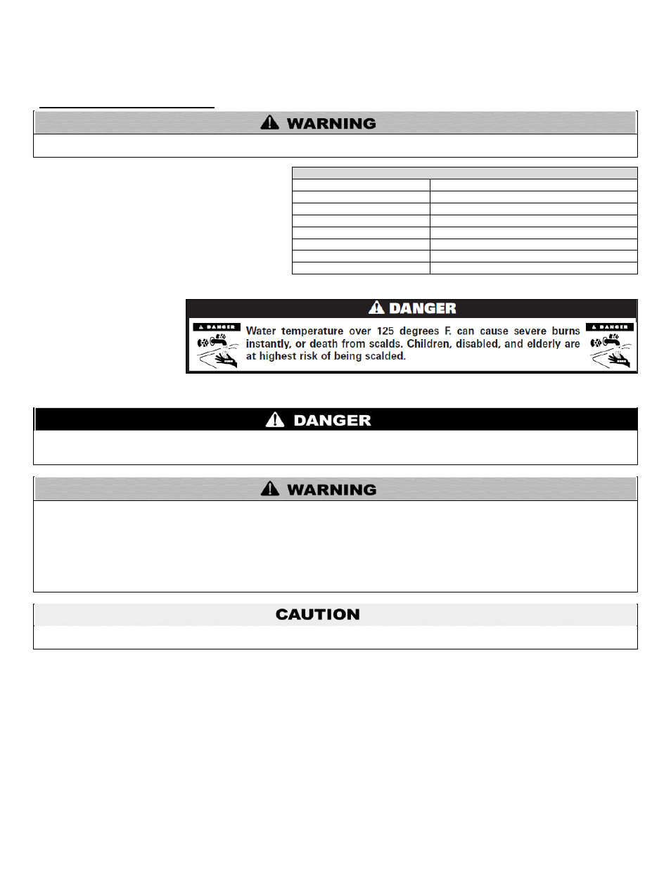
Hotter water increases the risk of scald injury. Scalding may occur within 5 seconds at a setting of 140
o
F (60
o
C). Water temperature
over 125
o
F can instantly cause severe burns, or death, from scalds. Children, disabled, and elderly are at the highest risk of being
scalded. See instruction manual before setting temperature at appliance. Feel water before bathing or showering!
This appliance can deliver scalding temperature water at any faucet in the system. Be careful whenever using hot water to avoid
scalding injury. By setting the thermostat on this appliance to obtain increased water temperature, you may create a higher potential for
scald injury. To protect against injury, you should install an ASSE approved thermostatic mixing valve (a device to limit the temperature
of water to protect against scald injury by mixing hot and cold water supply) in the system. This valve will reduce point of discharge
temperature in branch supply lines. This appliance was shipped with an ASSE approved thermostatic mixing valve. Install this valve
according to the directions in the mixing device container. DO NOT OPERATE THIS APPLIANCE WITHOUT AN ASSE APPROVED
THERMOSTATIC MIXING DEVICE. If this appliance was shipped without an ASSE approved thermostatic mixing valve, contact the
manufacturer.
The mixing valve is certified to ASSE 1017. It is not to be used to provide anti-scald service resulting from system pressure fluctuations,
and should not be used where more sophisticated compensating temperature controls are required.
Mixing Valve Specification
Min.
– Max. Hot Water Inlet Temperature
120 - 180
o
F (49 - 82
o
C)
Min.
– Max. Cold Water Inlet Temperature 39 - 80
o
F (4 - 27
o
C)
Max. Working Pressure
200 PSI
Min. Flow Rate
1 GPM
Outlet Water Temperature Range
85
– 130
o
F (29
– 54
o
C)
Min. Temperature Differential
27
o
F (15
o
C)
(Between Hot Supply and Outlet)
APPROXIMATE TIME / TEMPERATURE RELATIONSHIPS IN SCALDS
120
o
F
More than 5 minutes
125
o
F
1 ½ to 2 minutes
130
o
F
About 30 seconds
135
o
F
About 10 seconds
140
o
F
Less than 5 seconds
145
o
F
Less than 3 seconds
150
o
F
About 1 ½ seconds
155
o
F
About 1 second
Table 3