Harrington Hoists and Cranes (G)NTH Trolley User Manual
Page 35
35
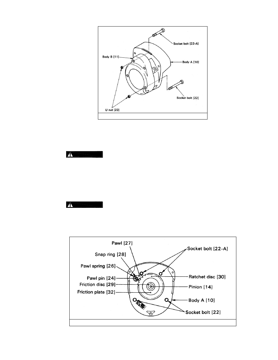
Figure 6-
6 Body “A” Assembly
15) Insert pawl pin [24] into the body A [10] and fix it with the U nut [25].
16) Apply machine oil to the pawl pin [24] and join pawl spring [26] and the pawl [27] respectively to it.
Fix the pawl with snap ring [28].
:
Make sure the pawl spring is fixed to the pawl and the snap ring is securely set
at the groove of the pawl pin.
17) Thread friction disc [29] on the pinion [14].
18) Wipe out any dirt on the friction disc [29], friction plates [32] and both sides of the ratchet disc [30]
and make sure that bushing [31] is properly soaked with oil. Then place the friction plate, bushing,
ratchet disc (while the pawl [27] is rotated counterclockwise), and friction plate respectively on the
friction disc. (Make sure that the pawl meshes with the ratchet disc properly.)
:
NEVER
apply oil since the brake is a “dry system”. Thoroughly wipe out any oil
and dirt on the brake. The gear of the ratchet should point at the pawl. Otherwise, the hand wheel
cannot be assembled later.
In case the bushing does not have oil inside, soak it in turbine oil for a day. Install it without wiping the
oil. Make sure that the pawl meshes with the ratchet disc properly.
Figure 6-7 Brake Assembly