Harrington Hoists and Cranes (G)NTH Trolley User Manual
Page 34
34
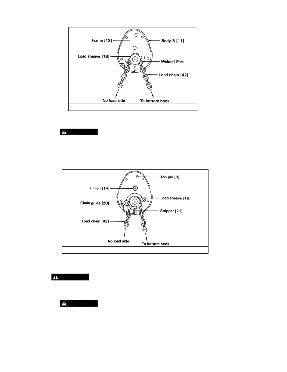
Figure 6-4 Load Chain Assembly
8) Put chain guide [20] (or guide rollers for ½ ton [20-A]) on the frame [13].
:
Fit the larger boss of chain guide [20] into holes on frame [13].
9) Put stripper [21] on the frame [13].
10) Insert pinion [14] shaft from its gear side through the frame [13] and into ball bearing B [16].
11) Insert top pin [3] into the frame [13] and put suspender to the top pin.
12) Clean and grease ball bearing A [15] and D [17-A] and insert into body A [10] (if being replaced).
13) Put the body A [10] with the ball bearings [15, 17-A] side down on the body B [11].
:
Make sure each part is completely set between body A [10] and frame [13].
14) Insert four socket bolts [22, 22-A] into the body A [10] and turn the whole body sideways. Then fix
the bolts with the U nuts [23] holding the U nuts with fingers.
:
Insert short socket bolts [22-A] to the upper holes and long socket bolts [22]
to the lower holes.
Figure 6-5 Chain Guide Assembly