Harrington Hoists and Cranes (G)NTH Trolley User Manual
Page 12
12
3.0 Preoperational Procedures
3.1
Trolley Adjustment
3.1.1
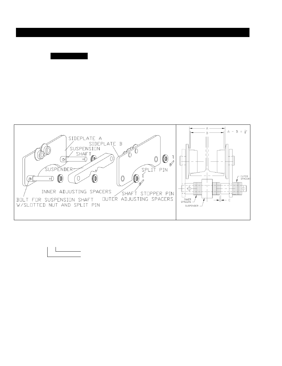
Before use, the manual trolley can be adjusted in increments of 1/8” by simply
inserting or removing adjusting spacers to fit a variety of beam flanges. To adjust the trolley, reference
Figures 3-1 and 3-2. Proceed with the following instructions:
1. Remove the stop pins and slide off side plate B and spacers from the suspension shafts.
2. Reinsert the appropriate number of inner spacers for the desired flange width (Table 3-1).
3.
Insert side plate “B” and external spacers and lock into place with the stop pins.
Note: Referencing Figure 3-2, the trolley wheel flange to wheel flange dimension (A) will be
approximatly 1/8” wider than the beam width (B). This will leave 1/16” clearence per side.
There will also be a clearence between the inner spacers and the sideplate (C). This
dimension will equal up to approximatly 3/8”.
Figure 3-1 Trolley Side Plate Assembly
Figure 3-2 Spacer Assembly
Note: Pages 13 and 14 give spacer arrangement information. Take note the number on spacers of inner side as
follows:
Example: 1 + 2
Number on Side Plate A
Number on Side Plate B