Gilderfluke&Co DMX-512, Serial, and MIDI Output Smart Bricks User Manual
Page 43
Using Z-Bricks with a BS-DMX-Tx or BS-Serial Smart Bricks:
A Z-Brick is a card that can be used with BS-DMX-Tx or BS-Serial Smart Bricks to add thirty-two digital out-
puts to them. The data for the Z-Brick comes either from the DMX-512 that is being received by the BS-
DMX-Tx or BS-Serial Smart Bricks or from the Eprom on-board the BS-DMX-Tx or BS-Serial Smart Bricks. With
proper buffering, any number of Z-Bricks can be added to a BS-DMX-Tx or BS-Serial Smart Bricks. Each adds
another thirty-two digital outputs to the BS-DMX-Tx or BS-Serial Smart Bricks.
The Z-BrickÕs thirty-two outputs are addressed on four consecutive eight bit channels. This means that
each Z-Brick needs four eight bit channels worth of data. The Z-Bricks can be addressed on any address
that is a multiple of four. The two HEXadecimal switches on the front of the Z-Brick are used to set the ad-
dress. The address is set using HEXadecimal numbers (a chart which shows both numbering systems is at
the rear of this manual). The upper switch is used to set the upper nibbleÕs address. The lower switch is
used to set the lower nibbleÕs address. Because the address has to be set on a four byte boundary, the
lower switch has only four usable ranges. These are labeled on the silkscreen as Ф0-3Х, Ф4-7Х, Ф8-BХ, and ÔC-FÕ.
Setting this switch to any of the four positions in these ranges are acceptable. i.e.: there are four detents
at 0, 1, 2 and 3 on this switch. Setting the switch to ANY of these positions counts as the position Ф0-3Х on
the Z-Brick.
The Z-Brick must be connected to the BS-DMX-Tx or BS-Serial Smart Bricks by a twenty position ribbon
cable. When the Z-Brick is being scanned, the LED on its front will flash at 1/4 the frame rate.
In all animation systems made by Gilderfluke & Company all output cabling on the Z-Brick is through
what we call ФJ-6Х standard output cables. These are forty wire cables which are made up of four identical
eight bit wide ÔchannelsÕ. A J-6 cable is often split up into four individual channels. As each channel also
includes a common power supply and ground wire, each Ô1/4 J-6Õ cable is made up of 10 wires, and can
be used to control eight individual ÔdigitalÕ (off/on) devices, or one eight bit wide ÔanalogÕ device.
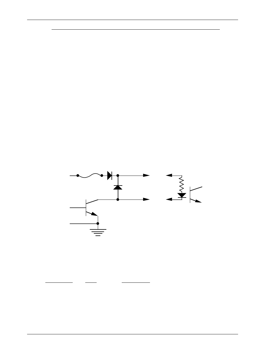
In all animation systems made by Gilderfluke & Company, all outputs are open collector switches to
ground. Flyback diodes are included in the outputs for driving inductive loads:
typical output
typical input
fuse
flyback
diode
supply
supply
To simplify wiring to any MACs animation system, the connectors used on the J-6 cables are what are
called Ôinsulation displacement connectorsÕ. These simply snap on to an entire cable, automatically Ôdis-
placingÕ the wire insulation and making contact with the wires within. This means that an entire forty wire
cable can be terminated in seconds. All connectors are polarized, to keep them from being plugged in
backwards. Although there are tools made specifically for installing these connectors, the tool we find
works best is a small bench vise.
Each J-6 cable is arranged in the following order:
wire number
color
wire function
1
brown
circuit ground
2
red
channel 0 data bit 7
3
orange
channel 0 data bit 6
4
yellow
channel 0 data bit 5
5
green
channel 0 data bit 4
6
blue
channel 0 data bit 3
7
violet
channel 0 data bit 2
8
gray
channel 0 data bit 1
G
ILDERFLUKE
& C
O
.¥ 205 S. F
LOWER
S
T
. ¥ B
URBANK
, CA 91502 ¥ 818/840-9484 ¥ 800/776-5972 ¥
FAX
818/840-9485
43 of 48