Gilderfluke&Co Sd-25 Audio Repeaters w/Amplifier User Manual
Page 3
Volume Controls:
A pair of small trimpots on the Sd-25 are used to set
the maximum audio output level from the MMC/Sd
card. The operating modes which ramp the audio up
and down can never exceed the level set by these
pots.
An additional pair of pots is used to set the levels for
the ʻmixerʼ inputs.
With the case top on or off, you can adjust these
pots using a small ʻtrimmerʼ screwdriver.
These trimpots are smaller than you. Do not use a
big screwdriver on them. Do not apply too much
force. They will break!
Mixer Inputs:
Two line level ʻmixerʼ inputs are available on version
1.6 and later Sd-25s. A line level audio signal from a
Sd-10 audio repeater, pre-amplified microphone or
any other line-level audio source can be plugged
into these two RCA jacks. Two trimpots can be used
to adjust the levels of the mixer inputs.
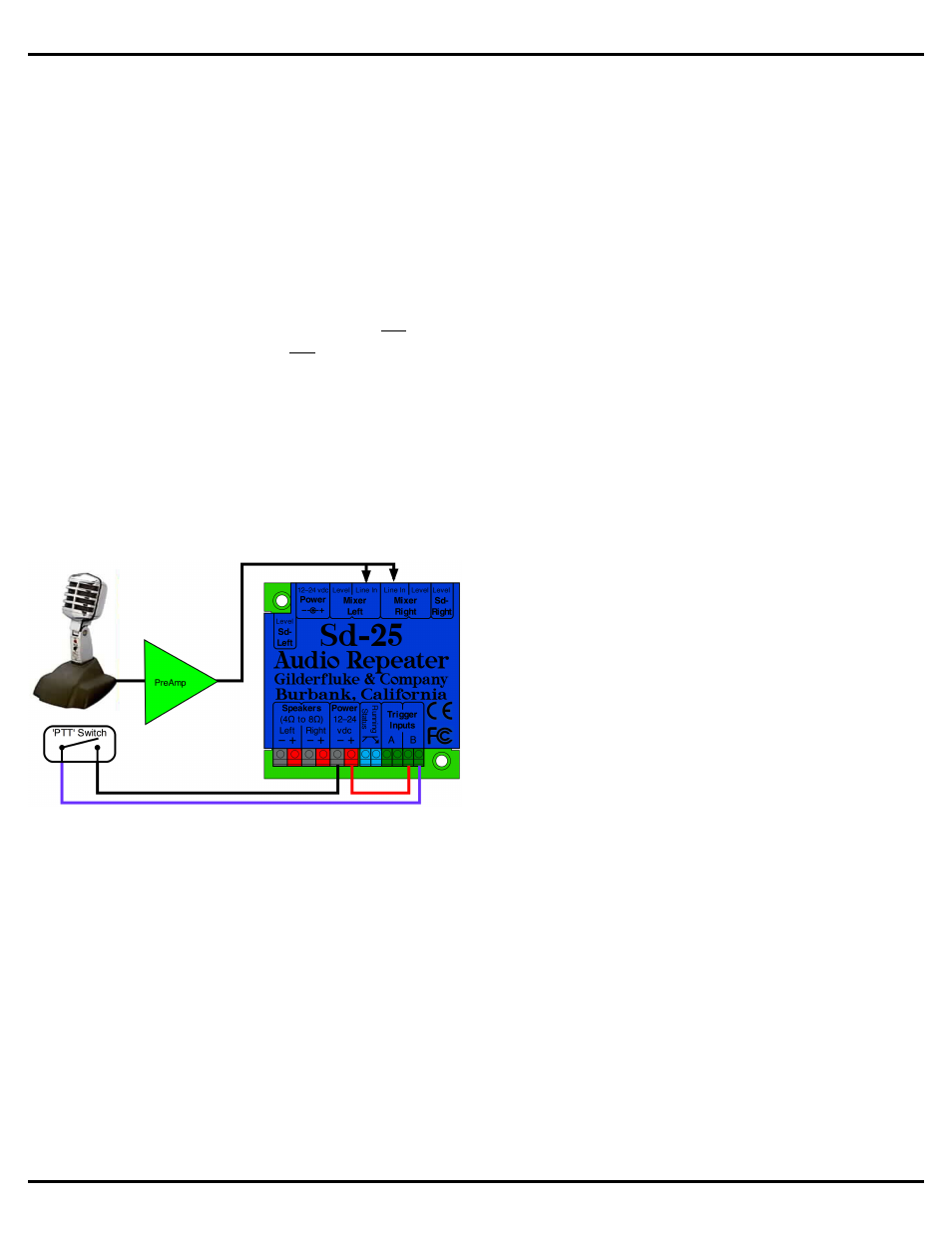
In this example, a preamplified microphone is fed
into the mixer inputs of the Sd-25. The ʻPush to Talkʼ
button on the microphone is fed into the ʻbʼ input of
the Sd-25. The Sd-25 is configured to ʻduckʼ the
audio from MMC/Sd card to a lower level when it
sees a closure on the ʻbʼ input. When the micro-
phone button is pressed, the Sd-25 ramps the pre-
recorded audio down to a lower level, and the mi-
crophone is used to make an announcement. When
the button is released, the prerecorded audio ramps
back up to the normal playback level.
Sd-25s earlier than hardware version 1.5 features
line level outputs instead of mixer inputs. If you need
line level outputs, these are available as a no-cost
factory option when you order a new Sd-25. To use
the line level outputs, just run a pair of RCA cables
to your amplifier (or amplified speakers), just as you
would if you were connecting a CD player. The line
level outputs are robust enough to drive head-
phones and small speakers directly.
Modulation LEDs:
The two ʻmodulationʼ LEDs, which are located in
front of the speaker screw terminals, blink to show
audio being reproduced. They pick up the audio sig-
nal coming from the repeater before the two volume
control pots, so they are not affected by adjusting
these pots or by the auxiliary ʻmixer inputs. Reduc-
ing the audio level through one of the ʻrampingʼ
functions will reduce the intensity of these LEDs.
Audio at too low a level will cause these LEDs to
completely extinguish. Normalize your audio before
loading it on the Sd-25 so that it is near 100%
modulation.
Sometimes additional safety system assurance
above and beyond monitoring the ʻStatusʼ output is
needed to confirm that the Sd-25 is actually playing.
An external solid state relay or optoisolator can be
attached in place of these LEDs. The safety system
can then monitor this to confirm that an audio signal
is indeed being generated. Contact Gilderfluke &
Company for more information on this sort of appli-
cation.
Status Output:
A single uncommitted optoisolator output is available
for remote monitoring of the Sd-25. It is ʻonʼ only
while the Sd-25 is playing a triggered or ʻforegroundʼ
SoundFile. It can be used to control ducking mixers,
relays, or whatever you need.
To turn on a light, motor, or other electrical device
while a triggered or foreground SoundFile is playing,
just wire a solid state relay to the status output.
Then wire the light, motor, or whatever you are con-
trolling to this relay. This can be used in a museum,
trade show, Point Of Sale (POS) and other applica-
tions.
In applications where a background audio SoundFile
that doesnʼt stop when a foreground SoundFile is
playing, the BGM SoundFile can be played from a
Sd-10 which feeds its audio into the ʻmixerʼ inputs of
the Sd-25.
Gilderfluke & Co.• 205 South Flower Street • Burbank, California 91502 • 818/840-9484 • 800/776-5972 • fax 818/840-9485
page 3 of 16 • © February 11, 2014 Gilderfluke & Co. DCM