Trigger inputs, Power supply, Sd-25 – Gilderfluke&Co Sd-25 Audio Repeaters w/Amplifier User Manual
Page 2
B
A
Running
Status
Inputs
Switch ‘b’
External power for Switches & Status
Battery
Left
Switch ‘a’
Power
9-24 vdc
Right
Speakers
Left
ʻBridgedʼ
Speaker
Connections
Br-MiniBrick4
Gilderfluke & Co.
Burbank, California
0 1
2 3
Record Go
Data
Trigger
9-24
vdc
Outputs
Outputs
Triggering from a
Control System
A
Inputs
B
Sd-10
of speakers, so long as the impedance remains
within limits.
If your speaker seems to clip out at an unusually low
level, it may be that the speaker protection circuitry
inside the crossover is confused by the digital output
of the Sd-25ʼs amplifier. If this is the case, we have
a small filter module available that can smooth the
signal the speaker receives.
The Sd-25ʼs amplifier is well protected from short
circuits and overheating. You can stick a screwdriver
right across the speaker terminals, and the Sd-25ʻs
amplifier will go back to work an instant after a fault
is removed. If the speaker impedance is too low and
you are running at a high volume level, the amplifier
may start to cut out. If you hear this, check the
power supply voltage. If the input voltage is drop-
ping, you might simply be drawing too much power
for the power supply and a larger supply may fix
your problem. If the power supply is OK, and you
canʼt increase the speaker impedance, then you
might simply be asking too much of the Sd-25ʼs
amplifier, and need to turn down the volume a tad.
If you wish to comply with FCC and CE standards
for radio frequency emissions, you should use
shielded speaker wires with the Sd-25. The shield
should be attached to the power supply ʻnegativeʼ
terminal, which is immediately adjacent to the
speaker terminals. This will not affect the sound
quality from the Sd-25, but will make the FCC and
CE folks happy. Shielded speaker lines were used
during all CE/FCC certification testing.
Bridged Amplifier: If you need a mono output with
more ʻoomphʼ, the amplifier in the Sd-25 can be
ʻbridgedʼ. Bridging will only have an effect with lower
impedance speakers You wonʼt hear a bit of differ-
ence if you are using an 8 ohm speaker. The only
audio which is amplified comes from the ʻleftʼ
sources (mixer and repeater). The wiring to ʻbridgeʼ
the amplifier is a little different than on a
linear amplifier. The speaker is wired in
parallel to both speaker outputs, and the
jumper inside the Sd-25 is moved to the
ʻbridgedʼ position. Wiring the speak-
ers for a ʻbridgedʼ output without
moving this jumper can damage the
Sd-25ʼs amplifier.
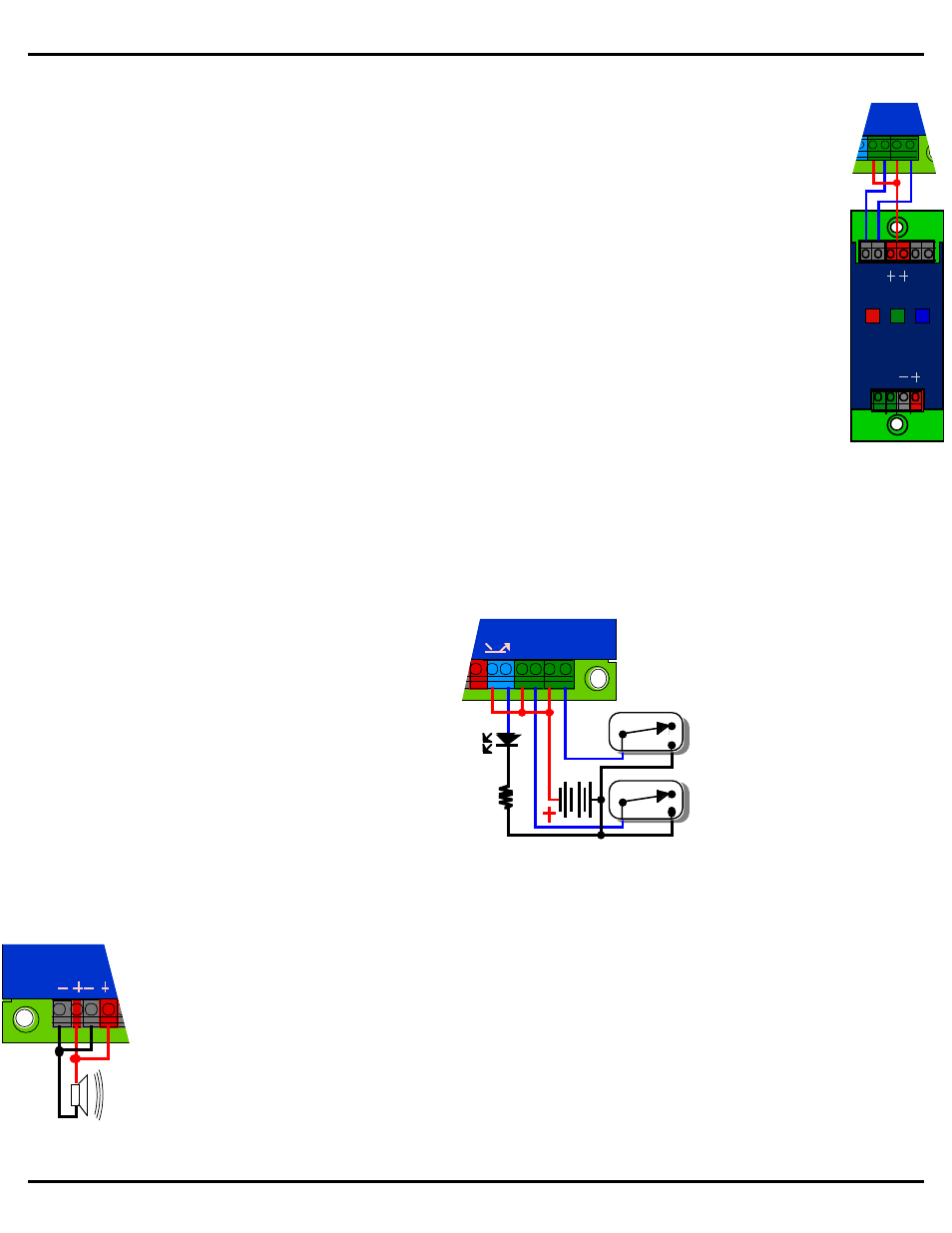
Trigger Inputs:
The trigger inputs can be used with any
switch. This can be a pushbutton, motion
detector, IR beam, step mat, a digital sig-
nal from a control system, or anything
else that will give you a ʻpowered switch
closureʼ. The trigger inputs are non-
polarized (they donʼt care which terminal
is positive or negative) and opto-isolated.
You must feed a DC voltage into them.
Just touching a pair of leads from a nine
volt transistor radio battery is a good test
of the inputs. As shown at the middle of
the last page, you can ʻborrowʼ some of
the power that is running the Sd-25 using
the adjacent screw terminals, or use a
separate isolated supply (as shown at
left). The power supply is shown as a bat-
tery, but can be any power supply from 9
to 24 vdc.
Not surprisingly, all Gilderfluke & Co. control sys-
tems are easy to attach to a Sd-25. A Br-
miniBrick4 is shown, but all of our systems are
wired in exactly the same way. The common posi-
tive is run to one side of both Sd-25 inputs, and the
control system outputs are wired right to the Sd-25
inputs.
The ʻInputʼ LEDs that are next to
the two Sd-25 inputs will light when
each input is active.
Power Supply:
The Sd-25 will run on any
voltage from 12 through
24 vdc. Whatever voltage
you use will also be used
to run the amplifier. If you
arenʼt using the amplifier,
the Sd-25 will run on less than 50 ma. Size your
power supply so it will provide enough current for
the volume you are planning to run at. The amplifier
will put out more power at 24 volts than it can at a
lower voltage. If using all 50 Watts of the amplifier
power, you will need to use a 24 volt supply rated at
least 60 Watts. If you hear clipping, the speakers or
power supply may be undersized for your applica-
tion.
The power supply can be attached through the 2.1
mm power jack, or the screw terminals. Power Sup-
ply voltages higher than 24 vdc can damage the
amplifier on the Sd-25.
Gilderfluke & Co.• 205 South Flower Street • Burbank, California 91502 • 818/840-9484 • 800/776-5972 • fax 818/840-9485
page 2 of 16 • © February 11, 2014 Gilderfluke & Co. DCM
Sd-25