Salamander Designs CL/PM2/B User Manual
Chameleon tv mount, Limited warranty, Install tv bracket + top brace
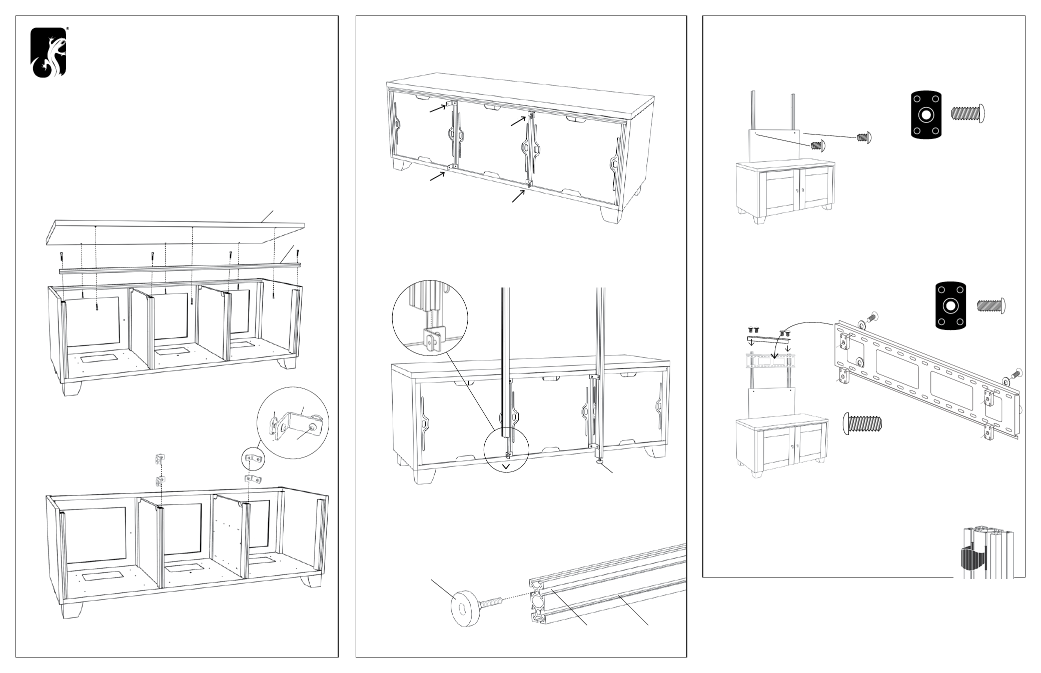
Top
LIMITED WARRANTY
Five full years Salamander Designs Ltd will repair or replace, at our option, any product defective in materials or craftsmanship. Salamander
Designs Ltd. will not be responsible for any damage to or destruction of other equipment consequential to our equipment failure. Defective
product must be given Return Authorization and is to be returned to the factory prepaid, in the original carton and packing material. Any
damage incurred in a shipment not in original packaging shall be the responsibility of the owner. Warranty repairs will be returned prepaid,
via UPS within the continental U.S.A. only.
Visit us at www.salamanderdesigns.com.
©2010 Salamander Designs Ltd. Doc No. 500-992 v11.10
8. INSTALL TV BRACKET + TOP BRACE
A.
Locate Large Bracket in FX 100/L Box. Loosely install hardware through holes
indicated (3/8’’ length screws, washers, and flat nuts).
B.
Install Large Bracket by sliding flat nuts down the front post channels, following
the black panel. Secure at desired position.
C.
Install top brace using four 3/4” screws.
9. FX100/L INSTRUCTIONS
Continue on to the instructions included in the box labeled FX100/L.
Note: Step 1 of the FX100/L instructions do not apply to your Chameleon product.
10. WIRE MANAGEMENT
After installing your components, gather wires/cables
and attach wire managers by clipping in post channels.
7. INSTALL BLACK PANEL
A.
Loosely assemble 3/4’’ length screw with flat nut as shown (2x).
B.
Install black panel by sliding the panel with flat nuts down the front post
channels then secure in place.
Flat Nut
(300-520)
Flat Nut
(300-520)
3/4” Screw
(300-010)
3/8” Screw
(300-010)
3/4” Screw
(300-010)
2. INSTALL BRACKETS
A.
Loosely assembly hardware as shown.
B.
Slide flat nut on the short side of the “L” bracket
down the vertical posts (2 down each post).
3. RE-ASSEMBLE
Re-assemble horizontal post, top and rear panels.
4. SECURE BRACKETS
Secure one bracket at the top and secure one at the bottom of both
vertical posts. Note the positions of the brackets in the drawing.
D.
Twist nut on leveler foot to the bottom of the foot. At the end of each
post screw the leveler foot into the end. Note: Screw the leveler on the
side with the Large Channel.
5. INSTALL POSTS
A.
Loosely assemble 3/8’’ length screw with a flat nut in “L” Brackets.
B.
Install by sliding posts into flat nuts in the large side channel of the posts.
C.
Secure in place after feet are installed (D).
1. DISASSEMBLE
A.
Remove rear panels.
B.
Disassemble top from frame using 5/32” hex key.
C.
Disassemble horizontal post using 1/4’’ hex key.
CHAMELEON TV MOUNT
TRIPLE WIDTH CABINETS
PM2
BEFORE YOU BEGIN
• This TV mount is intended for use with Flat-Panel TV 60” or smaller and a maximum weight of 175lbs. (79kg).
• Carefully inspect the mount for shipping damage or missing parts. If any damage is apparent or you are missing
parts contact Salamander Designs at 800-535-5659.
• Read ALL instructions before assembly. If you have any questions, please contact your installation contractor
or Salamander Designs.
• Use with products heavier than the maximum weight or larger than the size indicated may result in instability causing possible injury.
• Mounts must be attached as specified in assembly instructions. Improper installation can result in serious personal injury.
Large Side Channel
Small Side Channel
Leveler Foot
Backside of Cabinet
Flat nut
(300-520)
3/8” Screw
(300-518)
Horizontal Post
Long Side
D