Wiring diagrams for 9555 – Robertshaw 9555 User Manual
Page 5
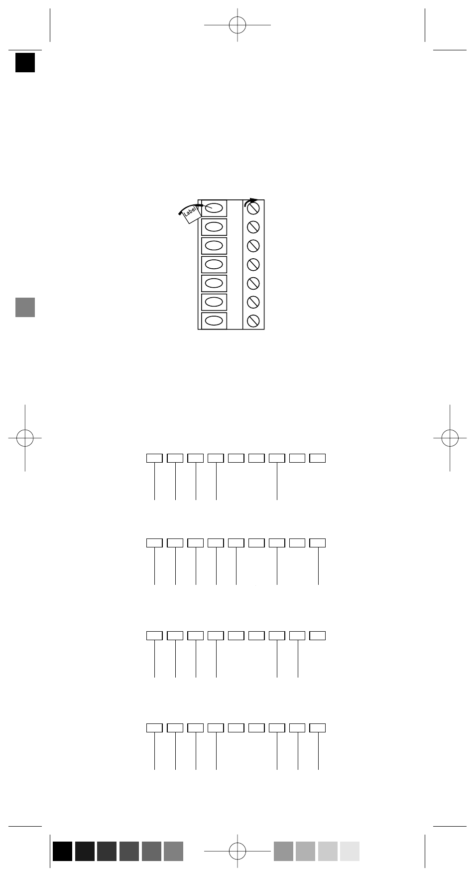
12. Terminal screws are already loose and ready for wire insertion.
Insert wires into terminal strip (Figure 5) matching the label to the
corresponding terminal (see Wiring Diagrams below). Tighten
screws.
13. Make sure wire connections are secure.
14. Push access wire back through opening.
5
O
Y1
W1
B
G
W2
Y2
W1
Wiring Diagrams for 9555
Typical 1 heat / 1 cool system
Typical 1 stage heat / 2 stage cool system
Typical 2 stage heat / 1 stage cool system
Typical 2 stage heat / 2 stage cool system
9555 WIRING SAMPLE #1
9555 WIRING SAMPLE #2
9555 WIRING SAMPLE #3
9555 WIRING SAMPLE #4
B
O
W2
Y2
C
R
W1
Y1
G
B
O
W2
Y2
C
R
W1
Y1
G
B
O
W2
Y2
C
R
W1
Y1
G
B
O
W2
Y2
C
R
W1
Y1
G
Figure 5
110-975D En.qxd 5/13/03 2:43 PM Page 5 (Black plate)
See also other documents in the category Robertshaw Water boiler:
- 800 (2 pages)
- 9400 (2 pages)
- 9401 (12 pages)
- 9400 (11 pages)
- 9405 (2 pages)
- 9405 (12 pages)
- 9415 (2 pages)
- 9415 (12 pages)
- 9500 (2 pages)
- 9500 (11 pages)
- 9505 (2 pages)
- 9505 (11 pages)
- 9520 (2 pages)
- 9520 (12 pages)
- 9550 (2 pages)
- 9555 (2 pages)
- 9560 (2 pages)
- 9600 (2 pages)
- 9600 (12 pages)
- 9610 (2 pages)
- 9610 (12 pages)
- 9615 (2 pages)
- 9615 (12 pages)
- 10-531 TAP-1 Adaptor (1 page)
- 200 SERIES (2 pages)
- 300-201 (2 pages)
- 300-202 (2 pages)
- 300-203 (2 pages)
- 300-204 (2 pages)
- 300-205 (2 pages)
- 300-206 (2 pages)
- 300-207 (2 pages)
- 300-208 (2 pages)
- 300-227 (2 pages)
- 300-229 (2 pages)
- 400 SERIES (2 pages)
- 8400-1 (2 pages)
- 8405-1 (12 pages)
- 8406-1 (12 pages)
- 8425-1 (2 pages)
- 8600-1 (2 pages)
- 8601-1 (12 pages)
- 8625-1 (14 pages)
- 900 SERIES (2 pages)