Mounting holes, Strip end of wires 5/16” if needed. 4 – Robertshaw 9555 User Manual
Page 4
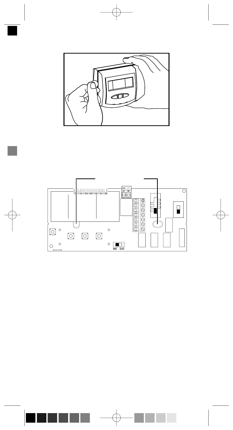
4. Remove the cover using a coin or screwdriver (Figure 3). Set aside.
5. Place thermostat against the wall at desired location. Make sure wires
will feed through opening (Figure 4) on base of thermostat.
6. Mark placement of mounting holes (Figure 4). Set base aside.
7. If mounting on drywall, tap plastic anchors into wall.
NOTE: ENCLOSED PLASTIC ANCHORS DO NOT REQUIRE A
DRILLED HOLE FOR DRYWALL.
8. Drill the marked holes using a 3/16" drill bit if mounting on a sur-
face other than drywall.
9. Align base with plastic anchors and feed wires through opening.
10. Secure base to wall with supplied screws.
NOTE: THE THERMOSTAT WILL MOUNT HORIZONTALLY
ON A SINGLE GANG JUNCTION BOX.
11. Strip end of wires 5/16” if needed.
4
Figure 3
Mounting Holes
WIRING
OPENING
W1
Y1
B
O
G
W
2
Y
2
NON
HP
Figure 4
110-975D En.qxd 5/13/03 2:43 PM Page 4 (Black plate)
- 800 (2 pages)
- 9400 (2 pages)
- 9401 (12 pages)
- 9400 (11 pages)
- 9405 (2 pages)
- 9405 (12 pages)
- 9415 (2 pages)
- 9415 (12 pages)
- 9500 (2 pages)
- 9500 (11 pages)
- 9505 (2 pages)
- 9505 (11 pages)
- 9520 (2 pages)
- 9520 (12 pages)
- 9550 (2 pages)
- 9555 (2 pages)
- 9560 (2 pages)
- 9600 (2 pages)
- 9600 (12 pages)
- 9610 (2 pages)
- 9610 (12 pages)
- 9615 (2 pages)
- 9615 (12 pages)
- 10-531 TAP-1 Adaptor (1 page)
- 200 SERIES (2 pages)
- 300-201 (2 pages)
- 300-202 (2 pages)
- 300-203 (2 pages)
- 300-204 (2 pages)
- 300-205 (2 pages)
- 300-206 (2 pages)
- 300-207 (2 pages)
- 300-208 (2 pages)
- 300-227 (2 pages)
- 300-229 (2 pages)
- 400 SERIES (2 pages)
- 8400-1 (2 pages)
- 8405-1 (12 pages)
- 8406-1 (12 pages)
- 8425-1 (2 pages)
- 8600-1 (2 pages)
- 8601-1 (12 pages)
- 8625-1 (14 pages)
- 900 SERIES (2 pages)