Warning – Rivers Edge RE602 JOURNEYMAN User Manual
Page 24
Check for parts online at
www.huntriversedge.com or call 800-450-EDGE (3343) M-F 8-5
Check for parts online at
www.huntriversedge.com or call 800-450-EDGE (3343) M-F 8-5
24
Operator's Manual
Rivers Edge One-Man Ladder Stands
ASSEMBlY INSTRuCTIONS (RE602)
Tools needed – two 7/16" wrenches
IMPoRtant assEMBlY tIP: do not tighten any nut and bolt combinations
completely until all parts are assembled together! Finger tighten plus one
turn of a wrench only! this will temporarily hold the lock nut on the bolt while
helping alignment of all parts! after all parts are assembled together, all nut
& bolt combinations must be completely tightened.
1. Attach the foot platform (1ML26) to the inside of side rails (SL61) using (2)
provided 1/4-20 x 2-1/4" bolts and locknuts. SEE fIGuRE 1. DO NOT tighten
all nut & bolt assemblies completely!
notE: Mesh surface should be on top with squared ends of platform clos-
est to side rails.
2. Attach the foot platform flat bars (SL8) to the inside of side rails and the
outside of foot platform using (4) provided 1/4-20 x 1-1/2” bolts and locknuts.
SEE fIGuRE 1.
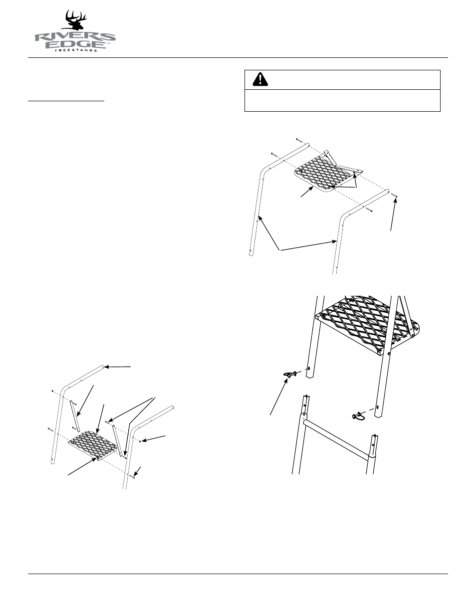
3. Attach the seat/tree blade frame (SL24) to the side rails using (4) provided
1/4-20 x 2-1/4” bolts and locknuts. SEE fIGuRE 2. You must now tighten
all nut & bolt assemblies. Be sure not to over tighten or crush tubing
when tightening!
notE: Mesh surface should be on top with tree blade at the end of the
side rails.
4. Sections are assembled on the ground in the following order: bottom section
(SL44 ladder); second section (SL43 ladder); third section (SL60 ladder); top
section (assembled top platform section). SEE fINIShED 15’ JOuRNEYMAN
lADDER.
5. With all sections assembled together on ground, secure all sections together
using (6) provided spring lock pins. Handle of spring lock pin must be put
to the outside of ladder side rails. SEE fIGuRE 3.
Figure 2
seat/tree
blade frame
Figure 1
1/4-20 x 2-1/4” bolts
locknuts
foot platform
side rails
foot platform flat bars
1/4-20 x 1-1/2” bolts
locknuts
side rails
1/4-20 x 2-1/4” bolts
locknuts
Figure 3
spring lock pins
WARNING
fOOT PlATfORM AND SITTING SECTION MuST AlWAYS
fACE ThE SAME DIRECTION, TOWARDS ThE TREE.