Rivers Edge RE602 JOURNEYMAN User Manual
Page 16
Check for parts online at
www.huntriversedge.com or call 800-450-EDGE (3343) M-F 8-5
Check for parts online at
www.huntriversedge.com or call 800-450-EDGE (3343) M-F 8-5
16
Operator's Manual
Rivers Edge One-Man Ladder Stands
4. Insert the assembled top platform section into the top ladder section with
mounting holes (SL54). Attach the (2) support braces (48064) to the outside
of side rails, foot platform and 4-step ladder section with mounting holes
using (2) provided 1/4-20 x 3-1/4" bolts, (2) 1/4-20 x 3" bolts, (2) 1/4-20 x
2-1/4" bolts, (4) steel washers and (6) locknuts. SEE fIGuRE 3. You must
now tighten all nut & bolt assemblies. Be sure not to over tighten or
crush tubing when tightening!
5. Attach the shooting rail (SR10) by setting rail down over studs on shooting
rail mounts. SEE fIGuRE 3. lubrication is recommended to prevent
binding and noise.
6. a. Attach the removable seat cushion (48819) to the top of seat frame. Wrap seat
straps or buckle straps around seat frame and secure together. Snap the side
release buckles together for buckle style seats. Pull straps tight so seat is not loose.
b. Attach the (2) provided 9" camo sleeves to the armrests and (1) 18" camo sleeve
to the shooting rail by wrapping around metal tubing and attaching Velcro together.
7. The remaining (2) ladder sections are assembled to the top ladder assembly
on the ground in the following order: bottom section (SL51 ladder); second
section (SL52 ladder); third section (SL54 ladder); top section (assembled top
platform section). SEE fINIShED 17' TIMBERShOT EXTREME lADDER.
8. With all sections assembled together on ground, secure all sections together
using (6) provided spring lock pins. Handle of spring lock pin must be put
to the outside of ladder side rails. SEE fIGuRE 3.
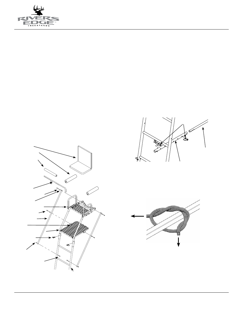
Figure 3
seat cushion
9" camo shelves
18" camo sleeve
shooting rail
1/4-20 x 3-1/4" bolts
steel washers
shooting rail mounts
1/4-20 x 3" bolts
support braces
locknuts
top platform section
spring lock pins
locknuts
1/4-20 x 2-1/4" bolts
4-step ladder section
w/ mounting holes
Figure 5
Figure 4
stabilizer bar
spring lock pins
extension tube
9. a. Attach the stabilizer bar extension tube (1ML23) to the second ladder
section mounting bracket using (1) provided spring lock pin.
SEE fIGuRE 4.
b. Slide the stabilizer bar (L17) into the extension tube and attach the two
pieces together using (1) provided spring lock pin. Spring lock pin must go
through both the extension tube and stabilizer bar at appropriate hole to
achieve desired distance from tree. Adjustment in length may be needed
when ladder is uprighted later in instructions. SEE fIGuRE 4.
10. a. Tie one end of the provided 9’ rope to the link welded onto the stabilizer
bar, just in front of the tree hugger. Be sure your double knot is secure.
SEE fIGuRE 5.
b. Tie one end of each of the provided 15’ ropes to the square tube side
rails, just in front of the welded on tree blades. Be sure your double knots
are secure. SEE fIGuRE 5.