Kasco Marine Robust-Aire User Manual
Page 8
8
from
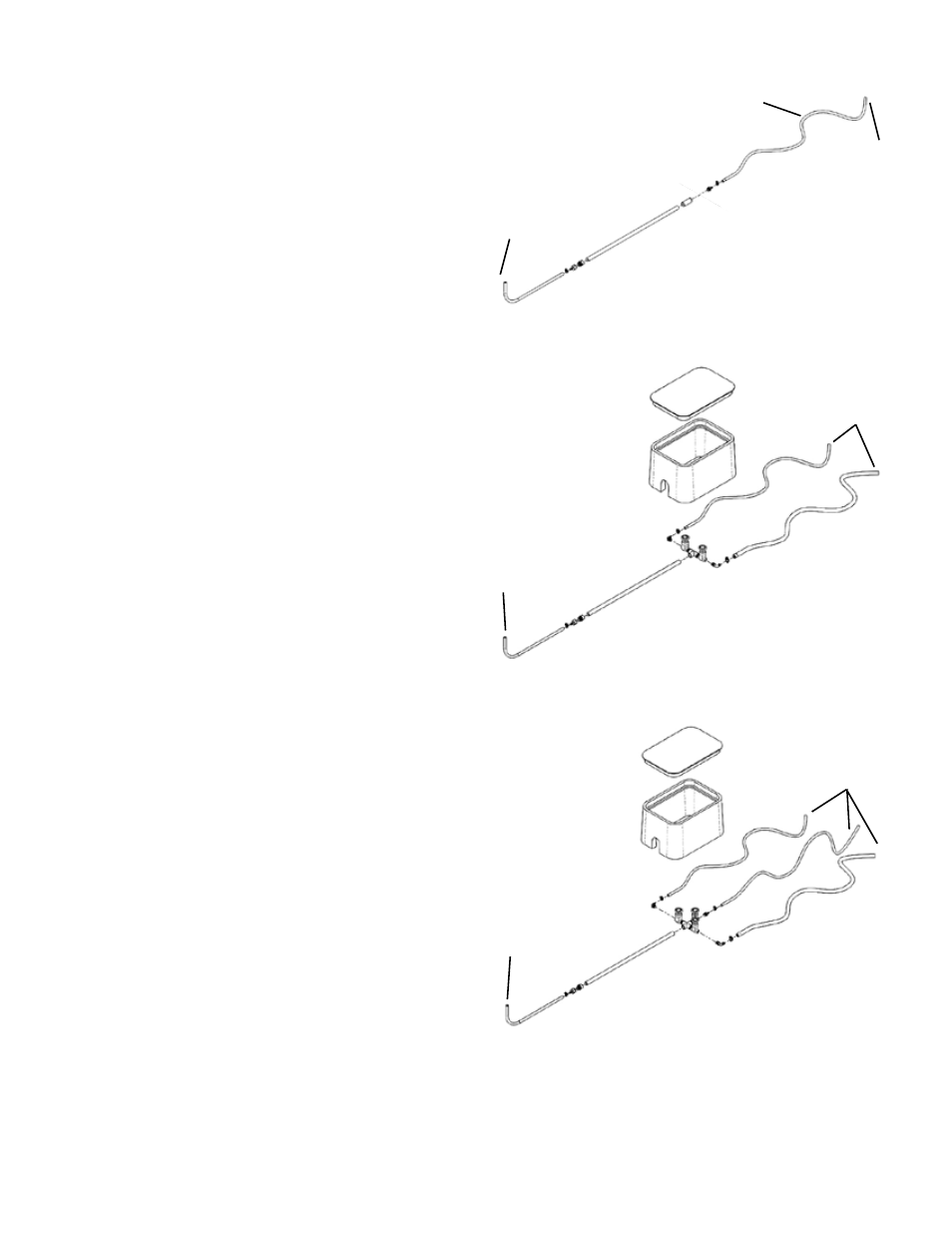
compressor
to
diffuser
3/8” or 5/8”
tubing
RM1
to
diffusers
valve
box
from
compressor
RM2
RM3
from
compressor
to
diffusers
valve
box
an area by shore to bury the included valve box. An
area at least 18” wide by 25” long x 13” deep will be
needed. Dig the area deeper and add crushed rock to
allow for drainage.
CAUTION: In northern climates where the ground
may freeze during the winter, be sure there are no
peaks and valleys in the PVC air line. Condensation
in the air line may freeze and can block the flow of
air to your diffuser and can cause damage to your
compressor.
For RA1 – RA3 systems, a single trench is all that is
required.
For RA4 – RA6 systems, either a single trench or two
separate trenches may be required depending on pond
size and diffuser placement locations.
Connect brass barb fitting to PVC adapter, applying
thread sealant to male threads on PVC adapter.
Connect barb fitting to rubber hose lead from
compressor and secure with hose clamp.
Connect PVC adapter and PVC pipe with primer and
glue. Add PVC pipe sections as needed to reach the
location of the remote manifold.
Prime and glue supplied manifold assembly to the end
of the PVC pipe run. Install 3/8” barb fittings or 5/8”
barb fittings depending on size of SureSink™ tubing
being run from the manifold to each diffuser. Apply
thread sealant to male threads of barb fittings. Attach
SureSink™ tubing to barb fittings and secure with
hose clamp.
When applicable, place valve box over manifold
assembly and fill in around box and entire length of
trench with the excavated dirt. The lid of the valve
box should be flush with the top of the ground surface.
When system has been completely installed, use the
valves (not provided on single diffuser systems) to
balance the flow to each diffuser.