Installation, Wiring diagrams – Fire Fighting Enterprises FIRERAY 5000 4-Head (Legacy) User Manual
Page 5
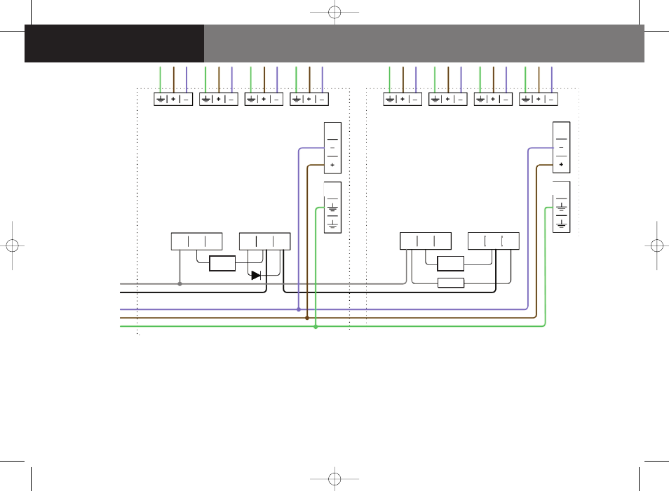
Wiring Diagrams
Installation
Wiring for all other System Controllers (where more than one System
Controller is on one zone)
(Not to be used for UL region installations. Please refer to supplied CD
for UL region installation multiple-System Controller wiring)
Wiring for a single System Controller or last System
Controller on one zone
ZONE -
ZONE +
SUPPLY -
SUPPLY +
EARTH/SCREEN
Components not supplied (Check Fire Control Panel
manufacturer for values):
• Fire Resistor (Some Zone and Switch Interface
Modules do not need a Fire Resistor - replace Resistor
with a short circuit.)
• Detector Continuity Diode
• End Of Line (‘EOL’) component
• Check operation of Fire and Fault connection on Fire
Panel
• ALWAYS use a separate screened 2-core cable for
each detector head
• CAUTION: For system monitoring – Do not use
looped wire under any terminals. Break wire run to
provide monitoring of connections
Apply a
voltage of
5V to 40V
to ‘Ext
Reset’
contact for
at least 2
seconds to
clear a
Latched
Fire
condition
DET 1
DET 2
DET 3
DET 1
DET 2
DET 3
DET 4
14V - 28V DC
DET 4
14V - 28V DC
FIRE
ConA
1
2
3
N/O
Fire
Resistor
Fire
Resistor
Ext
Reset
Ext
Reset
EOL
COM N/C
N/O COM N/C
FAULT
ConB
1
2
3
FIRE
ConA
1
2
3
N/O COM N/C
N/O COM N/C
FAULT
ConB
1
2
3
5
0044-034-01 - THESEUS UG - ENGLISH:0044-003-01 User Guide.qxd 23/06/2009 08:38 Page 5